


PM410-00xx0R17095
nv
Niko
sa Industriepark West 40, BE-9100 Sint-Niklaas, Belgium — tel. +32 3 778 90 00 — fax +32 3 777 71 20 — e-mail: [email protected] — www.niko.eu
EN
410-00xx0
7
Smart switch
Read the complete manual before carrying out the installation and activating the system.
1. DESCRIPTION AND OPERATION
The smart switch makes use of the Easywave RF protocol (Radio Frequency), through which different devices
including switches, receivers and gateways can communicate wirelessly. The smart switch contains one
(410-001X0) or two (410-002X0) switching contact(s) to switch the lighting (10 A each, combined maximum
16 A). If desired, extra controls can be added. These could be both wired push buttons and wireless controls
according to the Easywave protocol. By doing so, it can effortlessly replace any traditional single, multiway, or
intermediate switching, making it a transmitter and receiver in one.
Besides being able to switch its own contact, the smart switch is also able to switch other receivers operating
according to the Easywave protocol. This means that the smart switch is particularly useful for specific applications,
such as the renovation of heritage-listed buildings, expansions of existing installations where drilling or channelling
work is not permitted, offices with movable partition walls, … or to avoid complex cabling. The switch has a
feedback LED of which the operation can be set.
If you also have a Niko gateway (410-0100x), this switch can also be controlled via the Niko connected switch
app using your smartphone, tablet or smartwatch or via the web portal.
Each switch operating with the Easywave protocol can simultaneously control an unlimited number of receivers.
Each receiver can be controlled by up to 32 transmitters. For the smart switch, this means that a maximum of
32 wireless extension buttons can be connected.
The smart switch exists in two variations, depending on the number of push buttons:
Reference code
Number of push buttons/contacts
410-001x0
1
410-002x0
2
2. OPERATION AND USE
2.1. Range between the transmitters and receivers operating according to the Easywave protocol
Signals from devices for which a remote control is used, such as TVs, video and audio, will not be interrupted
by wireless transmitters. The transmitters do not require to be positioned towards the receiver. The indoor range
is ± 30 m. In open field, the range can be up to 100 m. The transmission range depends on the materials
used in the residence:
brick,
concrete
wood partitions and
plaster walls
reinforced
concrete
confined metal space
loss: 20-40%
loss: 5-20%
loss: 40-90%
loss: 90-100%
2.2. Mounting instructions and recommendations
Never install the transmitters and/or receivers:
• in a metal electrical cabinet, housing or netting
• in the immediate vicinity of large metal objects
• on or close to the ground
• in damp locations.
Position the receivers as close as possible to the transmitters. The presence of metal or damp in the walls can
have a negative influence on the signal range.
3. INSTALLATION AND PROGRAMMING
3.1. Installation of the cable(s)
3.1.1. Without extra controls and/or receivers
Connect the switch according to the wiring diagram below
N L L1 E1
N
L
N L L1 E1 L2 E2
N
L
After connection, the smart switch operates as a normal switch
3.1.2. With extra controls or receivers
3.1.2.1 With wired controls
The smart switch can be extended with an unlimited number of traditional wired push buttons. To do so, use
the diagram below. The push buttons are always switched in parallel.
L2 E2
N L L1 E1
N
L
170-0000x
170-0000x
Connect the contacts of the traditional push button to the L terminal and E1 terminal of the smart switch.
Use terminal E2 to extend the second channel of the smart switch (only applies to the 410-002x0) with
traditional push buttons.
3.1.2.2 With wireless controls
You can expand the smart switch with wireless push buttons according to the Easywave protocol. The procedure
is as follows:
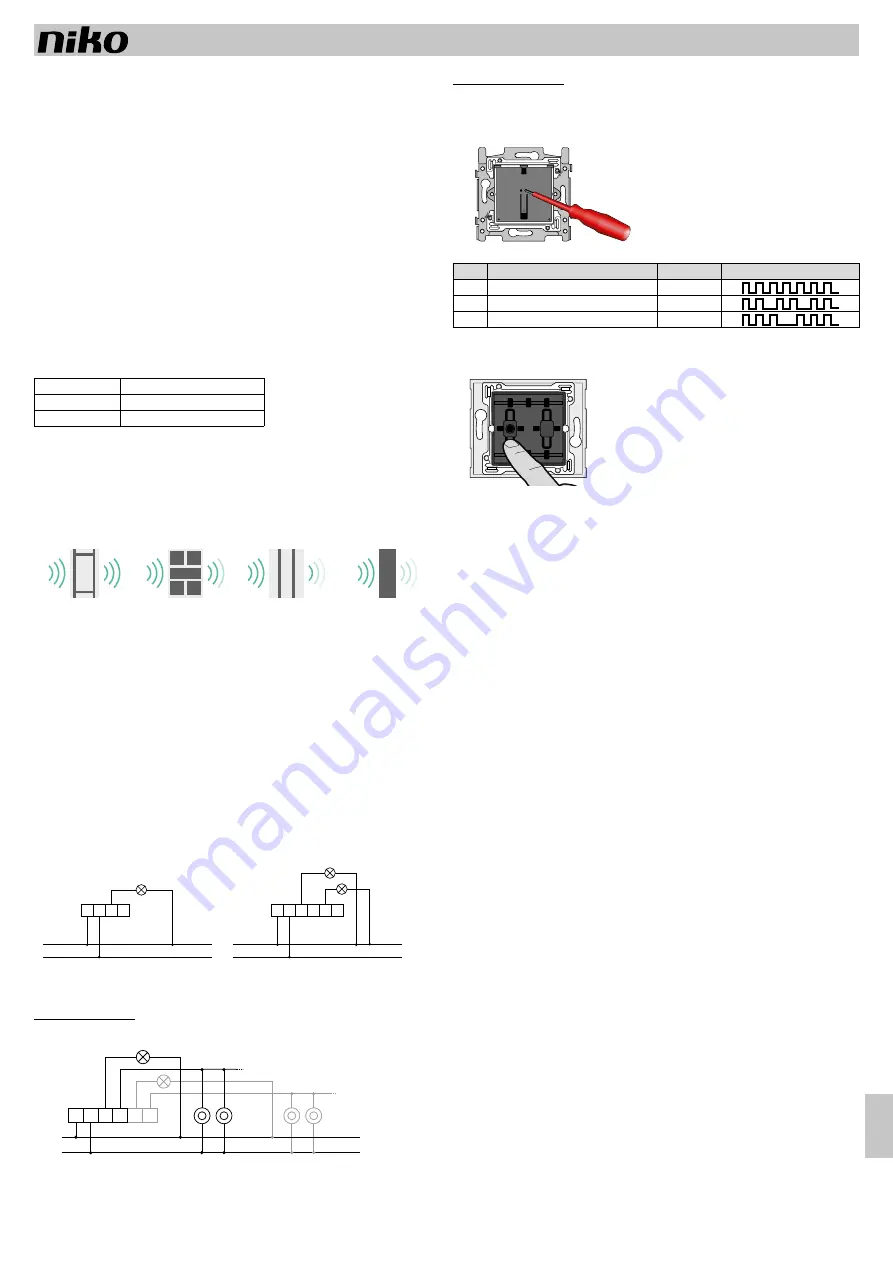
• remove the central plate from the push button
• only for 410-002x0: select the switching contact you want to program by pressing the corresponding control button
• briefly press (< 1.6 s.) the sunk programming button (Prog.) to switch between the different modes
PROG
PROG
The flashing of the programming LED indicates which mode you have chosen:
Mode
Position
Operation time
Light signal during programming
M1
Upper on / lower off
Infinite
M2
On/off on 1 button
Infinite
M3
Atmosphere/preset (see § 3.2)
Infinite
• one by one, control the transmitters which must partner with the receivers. The confirmation of a well-received
address is indicated by a long lighting time of the LED (Prog. – 4 s.). Per smart switch, a maximum of 32
transmitters can be connected. When reaching this maximum number, the LED will flash continuously
• exit the programming mode by briefly pressing the programming button repeatedly (< 1.6 s.) until you have
exited the programming mode (see table).
After a lengthy power interruption, the programming is maintained.
3.1.3. With extra receivers
You can expand the smart switch with receivers according to the Easywave protocol. The procedure is as follows:
• install the receiver you want to connect in programming mode
• press the control button of the smart switch to connect it to the receiver
• confirm the programming on the receiver.
3.2. Atmosphere/preset/all-off
When you connect a wireless switch in mode 3 to the smart switch (or any other compatible receiver), the
latter will operate as an atmosphere or preset control. This allows you to easily add an atmosphere or all-off
function to your installation.
After you have linked a wireless transmitter to the smart switch in mode 3, you can save an atmosphere and
re-activate it afterwards.
Proceed as follows to save an atmosphere:
• Set the receiver(s) linked in an atmosphere/preset (mode 3 for the smart switch) in the desired atmosphere
setting (or switch them all of if you want to save an all-off function).
• Now press for 3 seconds each transmitter linked in the atmosphere/preset with which you want to be able to
activate the set atmosphere. Now the atmosphere is saved and linked to the activated transmitters.
Activate the atmosphere
• Briefly press one of the wireless switches with which you saved the atmosphere, to activate the atmosphere.
3.3. Program the behaviour of the feedback LED
The feedback LED can operate in four different ways:
1. as a confirmation LED: the LED lights up when the contact is closed (standard)
2. as an orientation LED: the LED lights up when the contact is open
3. LED off: the LED never lights up
4. LED on: the LED always lights up
As standard, the LED will function as a confirmation LED. You can adjust the function of the LED at any time.
The procedure is as follows:
• switch on the lighting connected to the feedback LED
• for 10 seconds, hold down the programming button of the smart switch (Prog.) to proceed to the next behaviour.
The LED will briefly flash three times to confirm. The behaviour of the LED is now changed.
• repeat these steps until the feedback LED has reached the desired behaviour.
3.4. Delete controls from the memory
3.4.1. Delete selectively
With this option, you can delete one or more wireless controls which are connected to the smart switch from
the memory of the smart switch. The procedure is as follows:
• Ensure that the switched lamps of the smart switch are not switched on.
• hold down (> 1.6 s.) the programming button of the smart switch.
The LED (Prog.) begins to flash quickly
• press the control button of the wireless controls you want to delete.
The wireless control is deleted from the memory of the smart switch and the LED (Prog.) lights up for 4 s.
as confirmation
• If you want to delete multiple controls, press the control button of the wireless switch(es) you want to delete
from the memory
• exit programming mode by briefly pressing (< 1.6 s.) the programming button (Prog.) of the smart switch.


