background image

18

H5 NVR Series

 Users Manual

Chapter 4: 

Camera Installation

4.1 

Video/Power

NOTE:

 Connect all cameras locally 

before

 final placement to ensure that all 

components function properly.

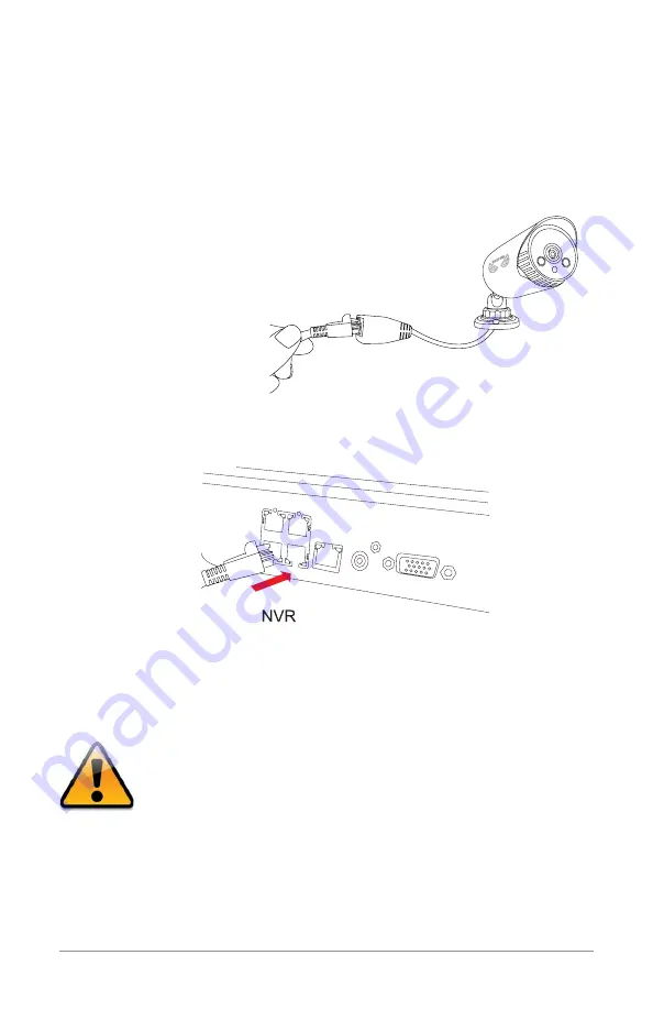
1.  Locate an included 60-foot PoE camera cable. 
2.  Connect one end of the cable to  

the connector attached to the camera.

3.  Plug the other end into a Video Input port on the back panel of the NVR.

4.  Repeat for each camera, noting the channel number each camera is  

plugged into.


* Cameras, additional cables, power adapters and  

  splitters only included in certain security kits. Check  

  the product packaging for detailed kit contents.

Make sure all cameras are working prior to mounting by 

connecting them as described in the section above. Once all 

cameras are confirmed to be fully operational, you can run 

the cables and mount the cameras at their final locations. 

Ethernet

IP Camera

Summary of Contents for H5 NVR SERIES

Page 1: ...www NightOwlSP com USER MANUAL H5 NVR SERIES 8 32 CHANNEL...

Page 2: ...cross all models so you may see features which are not applicable In addition you may see screen images that do not exactly match those on your display This manual was accurate at the time it was comp...

Page 3: ...3 Table of Contents TABLE OF CONTENTS...

Page 4: ...RA INSTALLATION 17 4 1 Video Power 18 4 2 Mounting the Cameras 19 CHAPTER 5 NVR INSTALLATION 21 5 1 Connecting to a TV via HDMI 22 5 2 Power 23 CHAPTER 6 GETTING STARTED 25 6 1 Startup Wizard 26 6 2 N...

Page 5: ...2 2 Image Control 43 7 2 3 Settings 44 7 3 Record Menu 45 7 3 1 General Playback 45 7 3 2 Events Playback Backup Files 46 7 3 3 Settings Recordings 47 a Basic 47 b Record Schedule 47 c Mainstream 48...

Page 6: ...13 USER INFORMATION 78 For your reference we have created an instructional video that explains the menu structure and functionality of your Night Owl recorder in detail Click on the icon at any time...

Page 7: ...7 Chapter 1 FCC Warnings CHAPTER 1 FCC WARNINGS...

Page 8: ...ference to radio communication However there is no guarantee that interference will not occur in television reception which can be determined by turning the equipment off and on The user is encouraged...

Page 9: ...9 Chapter 2 Safety Instructions CHAPTER 2 SAFETY INSTRUCTIONS...

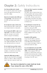
Page 10: ...e you move it When moving this device be sure to handle it with care Make sure there is good air circulation around the NVR This NVR uses an internal hard drive which generates heat during operation f...

Page 11: ...11 Chapter 3 Specifications images may vary CHAPTER 3 SPECIFICATIONS...

Page 12: ...t your mobile device complies with the following specifications Android 4 0 and above iOS 7 1 and above 3 2 Package Contents 1 x NVR Indoor Outdoor Cameras Bundles of Camera Cable Mounting Hardware an...

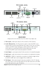
Page 13: ...an amplified speaker 4 Audio Input audio input allows for the connection of an external microphone 5 eSATA Port eSATA is a combination connection for external storage devices An eSATA or USB device c...

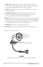
Page 14: ...eo files 9 Alarm RS 485 PTZ Port Alarm RS 485 port allows for PTZ camera connection and integration with your monitored security company Your security company must configure the NVR not Night Owl 10 U...

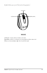
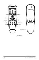
Page 15: ...ions images may vary 3 2 3 Mouse and Remote Diagrams MOUSE Left Select choose a field or button on screen Right Menu when in Live View click to display the bottom menu bar When in a menu window right...

Page 16: ...16 H5 NVR Series Users Manual REMOTE...

Page 17: ...17 Chapter 4 Camera Installation images may vary CHAPTER 4 CAMERA INSTALLATION SUPPORT VIDEOS...

Page 18: ...a Video Input port on the back panel of the NVR 4 Repeat for each camera noting the channel number each camera is plugged into Cameras additional cables power adapters and splitters only included in c...

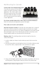
Page 19: ...ism Avoid direct exposure to weather Do not place the camera where rain or snow will hit the lens directly nor should the camera be placed so that the sun or bright light shines directly into the lens...

Page 20: ...secure 6 Once the base is screwed in place make sure that the camera is securely mounted by placing gentle pressure on the mount 7 Adjust the camera housing to point in the direction of the area you...

Page 21: ...21 Chapter 5 NVR Installation images may vary CHAPTER 5 NVR INSTALLATION SUPPORT VIDEOS...

Page 22: ...NVR Installation 5 1 Connecting to a TV via HDMI 1 Locate the included HDMI cable 2 Plug one end of the cable into the HDMI port on the back of the NVR 3 Connect the other end of the cable to an avai...

Page 23: ...on your TV or monitor to view the NVR If your TV does not have an HDMI port you will need to purchase a VGA video cable or compatible adapter For a VGA connection attach one end of the VGA cable to th...

Page 24: ...le power supply UPS plug the adapter cable into one of its output sockets Keep in mind Night Owl always recommends utilizing a surge protector to minimize the risk of damage caused to your NVR in the...

Page 25: ...25 Chapter 6 Getting Started CHAPTER 6 GETTING STARTED SUPPORT VIDEOS...

Page 26: ...d easy steps in detail After initialization you will be prompted to use the Startup Wizard Follow the on screen instructions to Create a system username and password Connect your NVR to a router that...

Page 27: ...D and connected your NVR to your router you can network your NVR by scanning the QR code which is located on the top of the NVR 6 3 Displays and Icons The following sections will describe the 3 main s...

Page 28: ...options or access the main menu Rearrange the channel order by left clicking and dragging individual channels to other locations in the on screen layout 1 Date and Time current date and time of the s...

Page 29: ...ct channel 17 32 to highlight it then click the button to display the Quick Add menu to add an IP camera when connected via PoE switch IP Address Domain enter camera IP Address and Domain Name Alias e...

Page 30: ...ion 6 3 5 Menu Screen Access the main menu by right clicking anywhere while in Live View and then selecting the menu icon At the menus you will be able to access settings and parameters for all aspect...

Page 31: ...31 Chapter 7 Menus and Settings CHAPTER 7 MENUS AND SETTINGS SUPPORT VIDEOS...

Page 32: ...from in the first dropdown box Copy then select the channel you would like to copy the information to from the second dropdown box To Click Copy when the proper channels have been chosen Be sure to Sa...

Page 33: ...e duration each channel is displayed during a sequential view You can select between 1 and 300 seconds per channel To begin the auto sequence feature click on the Auto Sequence icon which is located o...

Page 34: ...or Disable privacy zones on the selected channel Area Setup select the number of masks you would like to create or modify Mask Area a single Live View of the selected channel will be displayed with t...

Page 35: ...athered automatically from your ISP when connected Static modify these values if you are using a static IP address Information can be obtained from your router and ISP Media Port allows access to your...

Page 36: ...ll complete the manual automatically Manual mode will require manual configuration to complete the manual c Substream configure or optimize the video quality of your Live View Channel select the chann...

Page 37: ...ed while streaming The default setting is sufficient for most networks d Email Enable or Disable email alerts based on your alarm settings SSL Enable or Disable to send encrypted email alerts SMTP Por...

Page 38: ...TSP Enable or Disable RTSP to view live footage within compatible client software on a PC or Mac that is connected to the same network as your NVR Verify require users to enter a password when connect...

Page 39: ...k on the link to learn more Server set to the NIGHTOWL server when using the Night Owl free domain name server Domain set to the domain name you created when registering your DDNS User the UserID crea...

Page 40: ...re motion is detected You can select 10 seconds to 1 minute latch times from the drop down menu Alarm Out refers to alarms being sent onscreen via email full screen display of the alarm event and or p...

Page 41: ...etween 30 and 5 minutes Alarm Out refers to alarms being sent onscreen via email and or full screen display of the alarm event To receive the alarms you must left click the box to show a check mark wh...

Page 42: ...hat camera Manufacturer displays the manufacturer Device Type displays the type of camera connected to this channel Protocol will display if your protocol is private or public MAC Address displays the...

Page 43: ...p the image left to right of the selected channel by left clicking this box Backlight allows you to enable or disable the backlight function of the selected channel BLC Level allows you to select Low...

Page 44: ...ll display the selected channel s name when this box is checked Show Time will display the selected channel s time when this box is checked Position change the position of Channel Name while viewing i...

Page 45: ...en Channel select the channel you would like to playback footage from Type search All Normal Motion or IO videos to playback Playback Channel choose the desired channel to view footage from Start Time...

Page 46: ...ight click the mouse or click on the X to exit the playback screen 7 3 2 Events Playback Backup Files Search for video from triggered events and quickly backup the video files for future reference You...

Page 47: ...ubstream Pre Record Enable or Disable pre recording for this channel Pre recording is the amount of video captured prior to an alarm being triggered NOTE By default the NVR is configured to begin reco...

Page 48: ...ion Channel select the channel to configure Mainstream options Resolution allows you to adjust the resolution being displayed during streaming FPS increase or decrease the frames per second of the str...

Page 49: ...ault the Auto setting will overwrite the earliest footage once the HDD is full Choose one of the other options to overwrite footage at the end of the desired time duration starting with the earliest d...

Page 50: ...ct Month Day Year Year Month Day or Day Month Year Time Format select between a 12Hour or 24Hour display Language pick between ENGLISH or SPANISH language preferences Video Format NTSC or PAL formats...

Page 51: ...e applied the week of or an exact date Start Time select the date and time to apply the DST offset End Time select the date and time to remove the DST offset c NTP sync your NVR to the Network Time Pr...

Page 52: ...change the User Name Enable or Disable password access or create a new Password Permission select a new user profile e g user1 and press the Permission button to select which menus settings and playba...

Page 53: ...e device ID number if you are using multiple NVRs Device Name create a unique device name for easy reference Device Type product s model number Hardware Version your current hardware version Software...

Page 54: ...or backup files Log Type select the type of event log that you would like to Search for Each choice corresponds to an action or event that was triggered and noted within the system For example System...

Page 55: ...o 7 6 Advanced Menu Configure additional settings related to maintenance hard drive space and upgrades 7 6 1 Maintain Adjust settings related to default user access and reboot schedules Default User c...

Page 56: ...vent you would like to create a notification for Disk Full means you will receive a notification if the HDD is full Disk Error refers to the status of the HDD and will notify you if it crashes or has...

Page 57: ...ected automatically when this feature is enabled The default selection for the auto upgrade feature is enable Check For Updates check this tick box to periodically check for updated software versions...

Page 58: ...58 H5 NVR Series Users Manual CHAPTER 8 REMOTE ACCESS SUPPORT VIDEOS...

Page 59: ...u will need to have the following in order to be able to successfully connect the NVR to the Internet High speed Internet connection Router or modem with two open Ethernet ports PC Operating System Wi...

Page 60: ...bring up the Run window Type cmd and press the Enter key 2 In the command prompt window type ipconfig and press Enter Find the section named Ethernet adapter Ethernet or Wireless LAN adapter Wi Fi an...

Page 61: ...o the IP Address field this is the number that ends with 150 You may have to add placeholder zeros for any sections that do not contain three digits e g 192 168 1 150 192 168 001 150 2 Confirm that th...

Page 62: ...modem Follow these steps to determine basic information about your network 1 Select the Airport icon on your computer screen and choose the Open Network Preferences option 2 Choose Ethernet and select...

Page 63: ...the IP Address field this is the number that ends with 150 You may have to add placeholder zeros for any sections that do not contain three digits e g 192 168 1 150 192 168 001 150 2 Confirm that the...

Page 64: ...r s documentation to see how port forwarding works for your device This process may be referred to as Port Forwarding Port Mapping or Virtual Server Below are some general considerations to keep in mi...

Page 65: ...forward Media Port 9000 Web Port 2049 or 2051 or Server Port 2050 Private Port set to the same number you entered for the Public Port Port Type Protocol if your router has an option for both use TCP a...

Page 66: ...o to http www nightowlNVR com 2 Select the Registration button located at the top left corner of the page 3 Complete the New User Registration form Write down the UserID and Password information 4 Cre...

Page 67: ...gs Go to the General menu and then to the Network settings and the DDNS section 1 Set the DDNS field to Enable 2 Verify that the Server field is still set to NIGHTOWL 3 In the Domain field input the d...

Page 68: ...68 H5 NVR Series Users Manual CHAPTER 9 GLOSSARY SUPPORT VIDEOS...

Page 69: ...using the Internet IP Internet Protocol Protocol for standard communications across the Internet NVR Network Video Recorder PoE Power over Ethernet Run power and video over the same RJ 45 cable PPPOE...

Page 70: ...70 H5 NVR Series Users Manual CHAPTER 10 WARRANTY SUPPORT VIDEOS...

Page 71: ...ered by the same warranty as the original Product through the expiration date of the original warranty period Exclusions This warranty does not apply to the following parts or upon the following event...

Page 72: ...loss or theft related to the Product or to its use for any harm whether physical or mental related thereto Any and all claims or statements whether written or verbal by salespeople retailers dealers o...

Page 73: ...73 Chapter 11 Troubleshooting CHAPTER 11 TROUBLESHOOTING SUPPORT VIDEOS...

Page 74: ...o another outlet 5 Test the outlet with another plugged device such as a phone charger Remote control is not detected by the system Battery in the remote control is drained Install two fresh AAA alkal...

Page 75: ...lick in Live View to bring up the Volume control and ensure that the channel s are not low or muted Volume on external speakers not included is low or off Increase volume on external speakers not incl...

Page 76: ...76 H5 NVR Series Users Manual CHAPTER 12 CUSTOMER SUPPORT SUPPORT VIDEOS...

Page 77: ...a trip ONLINE www NightOwlSP com 24 7 Product Support How To Videos Manuals Firmware Updates etc EMAIL Technical Support support NightOwlSP com Sales Support sales NightOwlSP com PHONE English Spanish...

Page 78: ...78 H5 NVR Series Users Manual CHAPTER 13 USER INFORMATION SUPPORT VIDEOS...

Page 79: ...ber ___________________________________________________________ Internet Login Information Internal IP Address _______________________________________________________ Public IP Address _______________...

Page 80: ...www NightOwlSP com...
Reviews: