


SD210 Series
Operating & Safety Instructions
English/USA – 07/11
Issue 06
32
4.7.4
CALIBRATION
If a closer examination of the system is required, typically for testing and approval, the safe working
load should be placed in the cage, carefully weighing the test load to ensure accuracy. The addition of
a 5kg weight, to any of the four corners of the cage, should sound the alarm. If the alarm does not
sound, carefully inspect the weigh mechanism for signs of damage. All parts of the weigh mechanism
should be free to move, and the inspection should look for any impact damage that might have caused
the assembly to become disabled, for any reason. If the mechanism seems to be functioning correctly,
the adjustment of the weigh sensing micro-switch should be checked. A competent person, who has
the authority to perform such adjustments, must perform this. Adjustment must not be permitted by
anyone without the approval of the person responsible for the platform.
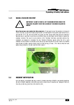
With the machine emergency stops ‘enabled’ and either the cage or base key switch turned ‘On’, first
check the cage weigh micro-switch is secure (
1
). If this is the case, the first step is to loosen the
securing screws attaching it to the support bracket, with the lock screw (
2
) below it backed-off,
allowing downwards movement. The tension in the weigh spring can now be released, by backing off
the two half-nuts securing it (
3
). With the spring mechanism relaxed, the bottom cage bracket comes
into contact with the cage support frame and will support the cage travel. This also gives the system
it’s full ‘over travel’, enabling the micro-switch to be checked. Make sure the switch is fully
compressed, now tighten the securing screws on the switch and ensure the lock screw (
2
) is wound
up into contact with the
switch, preventing any further
travel downwards. Lightly
apply lubricant to the support
assemblies (WD40, or
similar.), allowing thorough
wetting of the swivel bolts and
bearing assemblies, this will
reduce the hysteresis (i.e.
‘back-lash’) in the system and
ensure maximum accuracy.
The first (upper) half nut can
now be adjusted upwards until
the spring becomes partially
loaded. Continue adjustment
until the switch just loses
contact with the top cage
bracket, silencing the alarm.
The second (lower) half-nut
supporting the adjustment bolt
can be partially tightened to
lock the bolt in place.
The addition of a 5 kg weight should now be used to prove that the system detects the applied
overload, sounds the alarm and cuts off the machine operation. The sensitivity of the assembly is such
that the alarm will sound, slightly before the functions are disabled. The mechanism should be
adjusted to allow the alarm to sound and functions to be lost within this 5 kg limit. Once this has been
achieved, securely lock the lower half-nut (
3
).
The machine can now have the overload removed and the machine functions checked for correct
operation.
Summary of Contents for SD210 Series
Page 2: ......