10
|
ni.com
|
NI PXIe-4154 Calibration Procedure
The verification limits for voltage measurement depend on the actual voltage measured with an
external DMM, and are expressed as a percentage of DMM reading plus offset voltage. Refer to
Table 4 for more information.
Current Measurement Verification
To verify the current measurement of an NI PXIe-4154, measure a range of current test points
with an external DMM and a precision shunt. Divide the voltage across the precision shunt by
the actual resistance of the precision shunt. Compare these values to the values of the current
measured at the same current test points using the NI PXIe-4154. Refer to Figure 3 or Figure 4
for the configuration to verify current measurements while sourcing. Refer to Figure 5 or
Figure 6 for the configuration to verify current measurement while sinking.
Refer to Table 5 for a list of current test points for each range that you must request and measure
with an external DMM/precision shunt and the NI PXIe-4154 in order to complete verification.
To verify positive currents, use the NI PXIe-4154 channel as a source. For example, in the 1.5 A
range on Channel 1, program the NI PXIe-4154 to output 375 mA, 750 mA, 1.125 A, and 1.5 A
while setting the voltage limit to its maximum value. Use an external DMM/precision shunt and
the NI PXIe-4154 to take a current measurement at each test point. Compare the measured
values against each other.
To verify negative currents, use an external current source to force Channel 0 of the
NI PXIe-4154 to sink current. For example, in the 3 A range on Channel 0, program the
NI PXIe-4154 channel for 0 V output and program the external current source to output 750 mA,
1.5 A, 2.25 A, and 3 A. Channel 0 will be sinking current, so its measurements will be negative
currents. Take a current measurement at each test point using both an external DMM/precision
shunt and the NI PXIe-4154. Compare the measured values against each other.
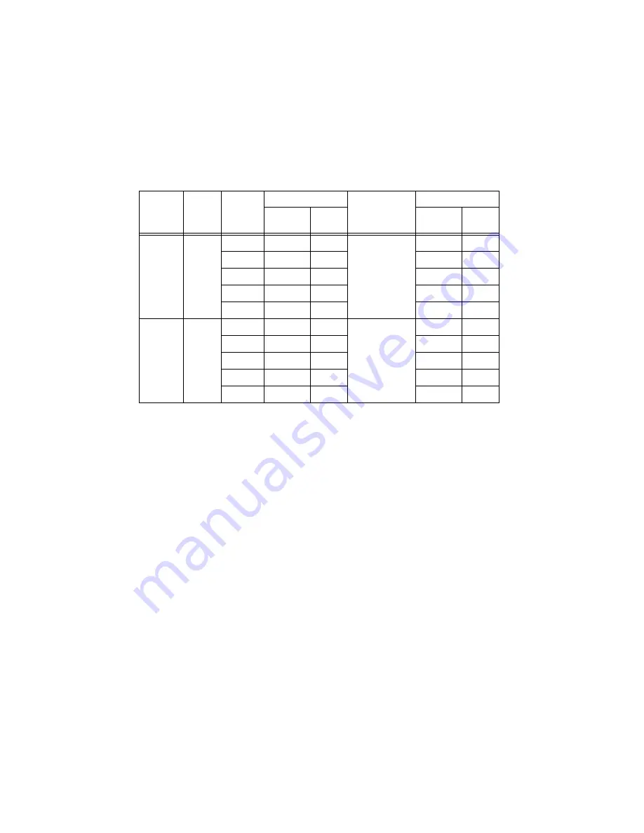
Table 4.
NI
PXIe-
4154 Voltage Measurement Verification Points
Channel
Range
Test
Point
Measured Voltage
Test Limit
Reported Voltage
As
Found
As
Left
As
Found
As
Left
0
6 V
0 V
0.025% + 2 mV
1.5 V
3 V
4.5 V
6 V
1
8 V
0 V
0.05% + 2.5 mV
2 V
4 V
6 V
8 V


