3
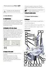
Fig2-1
A. vertical shaft spring
B. handle valve lock button
C. hexangular shaft
D. tool head
E. clamping jaw
F. turntable
G. pedal assembly decal
H. column tilting pedal
I. clamping pedal
J. bead breaking pedal
K. turntable rotation pedal
L. crowbar inserting hole
M. wheel supporting rubber
N. bead breaker blade
O. bead breaker blade handle
P. bead breaker arm
Q. clamping cylinder
R. bead breaker cylinder
T. air tank
U. column
V. inflation gauge container
W. horizontal arm
X. lock cylinder
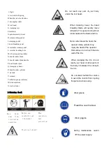
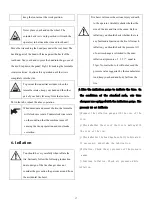
2.3warning decal
Electrical shock!
Do not reach any part of your body
under the tool head.
When breaking bead, the bead
breaking blade will quickly move
leftwards. The operator should not
stand between the blade and tire.
Note: when break the bead, the
opened clamp cylinder may
injury the hand of the operator.
Remember, do not touch the side
wall of the tire.
When clamping the rim, do not
reach your hand or other parts of
the body in between the clamp &
the rim.
Do not stand behind the column
to avoid the column from injuring
the persons when swing.
Wear gloves.
Read the user manual.
Wear goggles.
During maintenance, switch
off the power supply.
Keep
hand
away from
tire during
operation
Before use,
carefully read
the manual.
When
operation,
wear
protection.
Summary of Contents for TC-1300
Page 1: ...3456789 C61CN...
Page 36: ...35...


