9
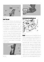
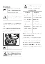
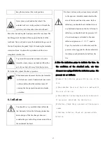
Fig 4-8
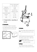
4.2.14 Air test:
After connect the air source, press down the lock
valve press button Fig2-2 to lock the horizontal
arm. Step down column tilting pedal (Fig2-11)
and the column will tilt back by about 25 º. The
tilting speed of the column has been set to be about
2 seconds before the machine is delivered out of
the factory. After long us, the speed will become
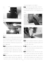
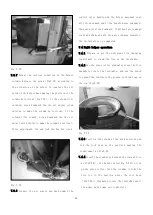
too slow or too fast. You can use the speed adjust
valve at the two head of the push-out cylinder.
Release the nut and clockwise adjust the speed of
the screw to be slow and counterclockwise adjust
the speed of the screw to be fast. After adjustment,
tighten the nut.
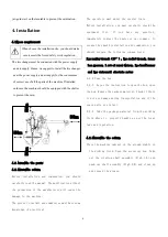
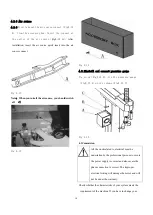
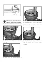
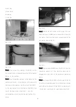
Fig 4-9
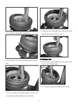
Fig 4-10
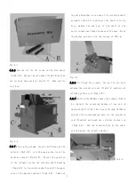
4.2.15 Install the bead breaker arm
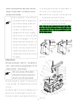
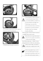
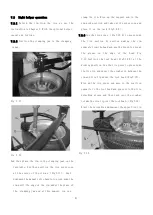
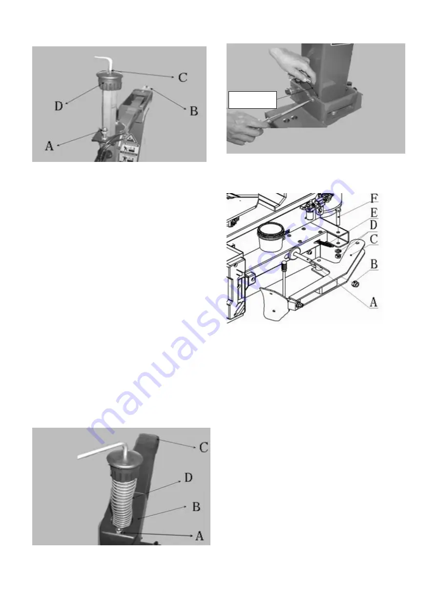
Fig 4-11
4.2.16 Unscrew the stop nut (Fig4-11 B)from the
top end of bead breaker piston rod and unscrew the
bolt connect on the machine cabinet(4-11 F)
(4-11
D). As per the instruction of Fig4-11, insert the
bead breaker blade (4-11 C)through the cylinder
piston rod(4-11 A). Hang one end of the bead breaker
arm spring(4-11 E)on the machine cabinet and then
insert the bolt(4-11 F) through the machine cabinet
and blade and use the nut and flat washer(4-11 D)
and bolt (4-11 F)to connect and fix. Tighten the
stop nut(4-11 B)and bead breaker cylinder piston.
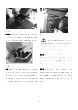
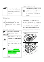
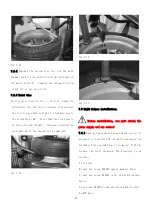
Hang the other end of the bead breaker arm spring
(4-11 E)Fig 4-11 on the spring pin shaft(4-12 A)
L=0.3mm
Summary of Contents for TC-1300
Page 1: ...3456789 C61CN...
Page 36: ...35...


