19
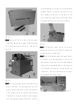
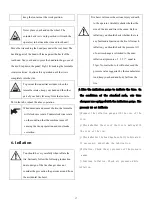
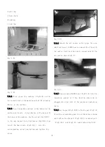
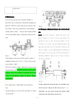
Fig 7-1
Fig 7-2
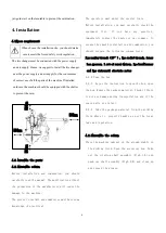
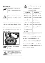
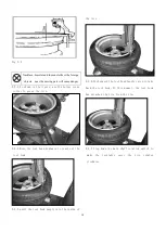
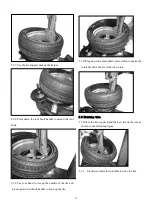
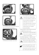
7.1.1 There is the installation hole prepared at the
back of the base plate of the machine cabinet of each
machine that can handle the tire more than 20″.
Before installation, detach the side panel and then
the T rubber plug.
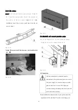
7.1.2 Open the package box of PL330 helper and then
check whether the spare parts is are intact as per
the packing list Fig 7-2. And then take out the base
frame assembly(Fig7-1)and detach the screw and
washer on it.
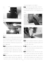
7.1.3 Push the base plate of the base assembly into
the machine cabinet from left back, making the
thread hole align to the reinforcement hole. Use
the bolt and washer to fix(Fig7-2).
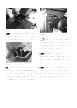
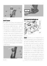
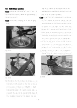
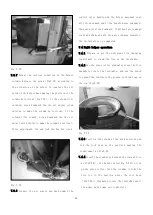
7.1.4 Place the main frame support(Fig7-3 A)
on the base assembly
Fig 7-3
. Align and use the screw
unscrewed before Fig(7-3) to fix. Remind not too
tight.
Fig 7-3
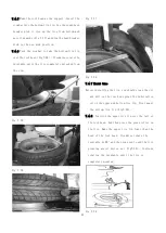
Fig 7-4
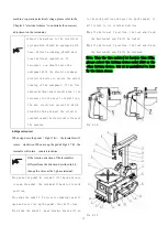
7.1.5 Use the fix bracket(Fig7-4 A)to connect the
main frame support with the machine cabinet and
insert the screw to fix.
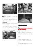
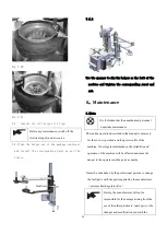
7.1.6 Use the Y Tee to connect the air source
(Fig7-5 A)and the other end is connected with the
helper pressure valve inlet.
7.1.7 Connect the air route. Insert the tire press
roller connect rod(Fig 7-6 A)into the rotating
arm rotating shaft hole(Fig7-6 B). Operate the
handle direction changing valve to make the tip of
the tire press conic roller align with turntable
Summary of Contents for TC-1300
Page 1: ...3456789 C61CN...
Page 36: ...35...

