23
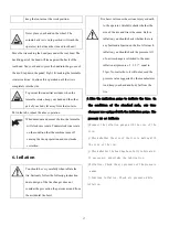
F ø8 Y Tee
J base plate
H cushion
I tool box
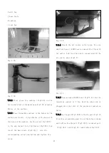
Fig 7-18
Fig 7-19
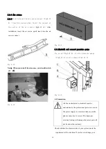
7.3.2 First place the cushion ( Fig7-18 ) on the
horizontal steel on the machine as Fig7-19, aligning
4holes of the cushion.
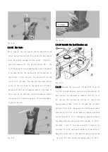
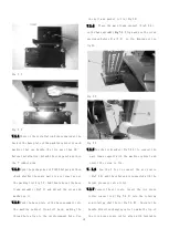
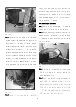
7.3.3 Place the machine cabinet of the helper on the
cushion vertically ,Align 4holes of the base with
the holes of the cushion. Use the screw(Fig7-18 D)
to fix and install into the 4holes(Fig7-20)
,And
insert the base plate(Fig7-18 J) into the
corresponding screw from bottom and tighten the
screw.
Fig 7-20
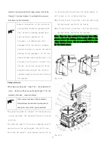
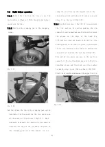
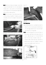
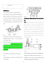
7.3.4 Detach the air source outlet pipe. Use one
small section of φ8PU hose to connect the Y Tee with
the outlet. And the other end is connected with the
air source pipe(Fig7-5)
Fig 7-21
7.3.5 Plug one end ofφ8PU hose(Fig7-5 A)into the
remaining connect of Y Tee. And the other end is
plugged into the inlet of the pressure regulation
valve.
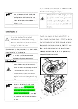
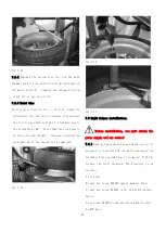
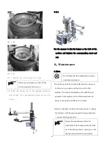
7.3.6 Use the part(Fig7-18 B)to fix the part(Fig7-18
A)on the corresponding position of the helper column
and tighten. Use the part(Fig7-18 C)to connect part
(Fig7-18 I) and(Fig7-18 )and tighten(Fig7-22).
Summary of Contents for TC-1300
Page 1: ...3456789 C61CN...
Page 36: ...35...

