www.nextups.eu
25
E
n
g
lish
active alarms before continuing. See “Troubleshooting”
7.
Verify that the UPS is operating normally and any load is
powered.
8.
If optional
EXBs
are installed, see “Configuring the UPS for
EXBs
” to set the number of installed
EXBs
.
9.
To change any other factory-set defaults, see “Operation”
Online
series recommends setting the date and time.
At initial startup, the UPS sets system frequency according to
input line frequency (input frequency auto-sensing is enabled by
default). After initial startup, auto-sensing is disabled until
manually re-enabled by output frequency setting.
At initial startup, inut voltage auto-sensing is
disabled
by default.
When manually enabled by output voltage setting, at the next AC
startup the UPS sets output voltage according to input line
voltage. After the subsequent startup, auto-sensing is disabled
until manually re-enabled by output voltage setting.
10.
If you installed an optional REPO, test the REPO function:
Activate the external REPO switch. Verify that status change on
the UPS display.
Deactivate the external REPO switch and restart the UPS.
4.6 Parallel Installation and Operation
4.6.1 Brief introduction of the redundancy
The parallel structure is 1+1.As long as the UPS is equipped with
parallel cables, up to 2 UPSs can be connected in parallel to
configure a sharing and redundant output power.
4.6.2 Installation and operation
How to install a new parallel UPS system:
1)
Before installing a new parallel UPS system, user need to
prepare the input and output wires, the input and output
breakers, and the parallel cable.
Summary of Contents for LOGIX II RT NETPACK 10000VA
Page 1: ...NEXT UPS Systems LOGIX II RT 6000 10000 NETPACK Installation and user manual English...
Page 4: ......
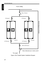
Page 31: ...www nextups eu 27 English Figure 4 5 a Parallel systerm wiring diagram of LOGIX II 6000 1000...
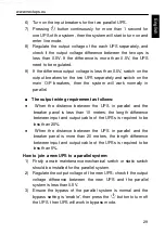
Page 32: ...www nextups eu 28 English Figure 4 5 b Parallel System Installation Diagram...
Page 43: ...www nextups eu 39 English...

