4.
Alignment and Measurement
4.3.
Measurement and Display Con guration in Detail
In this section the Control Software and its menus giving access to the control options are ex-
plained. Figure 4.1 on page 22 shows the measurement window of the A
·
P
·
E
scout
Link
Control
Software that is displayed when you initially start the software (in this particular case with no
Pulse
Scout2
optical head connected).
4.3.1.
"FILE" Submenu
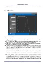
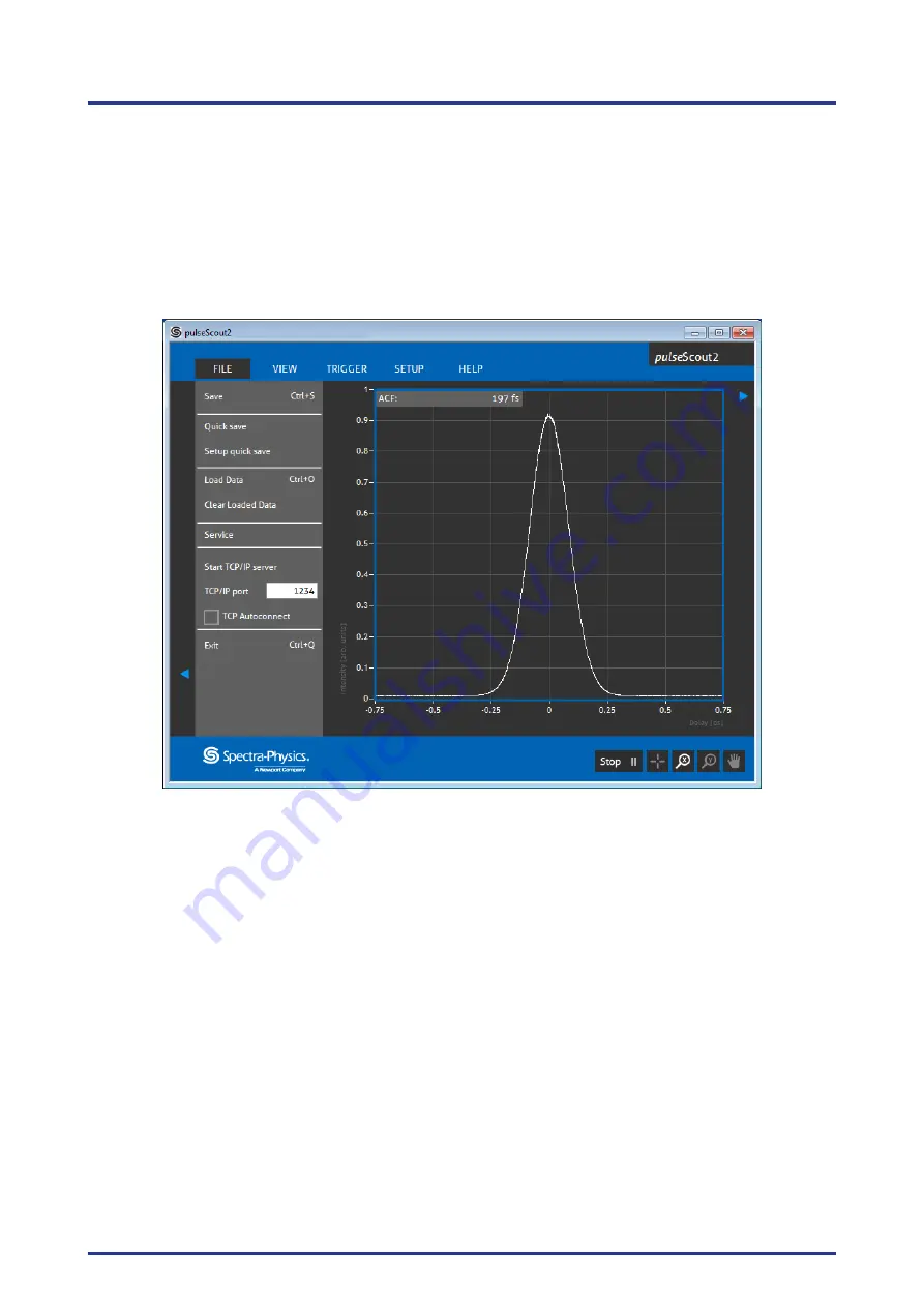
Figure 4.8.: File submenu
"Save":
Opens a le dialog and allows to choose a le name and location to save the current
autocorrelation trace displayed in the measurement window.
"Quick save":
A le name is automatically generated (containing time and data) and the raw
autocorrelation trace is saved to the user de ned folder.
"Setup quick save":
Chooses a default le name and location for the "Quick save" function.
"Load Data":
Loads and displays previously made autocorrelation traces. The loaded trace is
shown simultaneously with the current measurement for comparison and is highlighted in
another color.
"Clear Loaded Data":
Clears loaded data from the measurement window.
"Service"
: The service menu contains advanced settings and is not available to the user.
"Start TCP/IP server":
Starts the background server to control and read out the
scout
Link
re-
motely via TCP/IP. Note that TCP/IP communication may be restricted by your IT policy!
Please contact your local administrator if necessary. For further information on commands
and details to remote control the
scout
Link
refer to Appendix B on page 51.
"TCP/IP port":
Selects the TCP/IP port on which the
scout
Link
server listens for commands.
Pulse
Scout2 Version 1.1
29
July 2015

