4.
Alignment and Measurement
4.
Alignment and Measurement
After having connected all components of the system and installed the
scout
Link
Control Software
you are ready to start alignment and the rst measurement. Proceed as follows:
1. Fasten the optical head on your optical table at a place where you can easily direct the laser
beam nearly perpendicularly into the alignment aperture and handle the control elements.
Ensure that the computer screen with the
scout
Link
Control Software can be seen from the
position of the alignment.
2. Turn the system on by operating the power switch on the
scout
Link
controller.
4.1.
Communication Setup
After starting the
scout
Link
Control Software it automatically tries to initiate a connection to
the
scout
Link
controller. A communication between the software and the
Pulse
Scout2
has been
established when the serial number of the unit is shown in the window title.
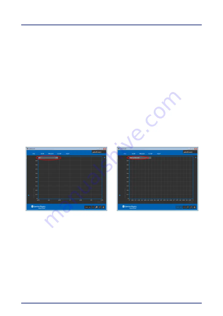
If communication is established the info window displays the status "ACF: 0 fs" in the upper left
corner of the measurement window (see Figure 4.1 (left)).
Figure 4.1.: Control Software start up window with established connection (left), and with failed
connection (right)
If the
scout
Link
is not properly connected or the initialization has failed the info window shows
the status "Not connected" (see Figure 4.1 (right)). In this case check the cable connections and
make sure the
scout
Link
is switched ON. If this is the case, try again to initiate communication to
the
scout
Link
controller by switching it off and back on again. Before you proceed with the next
steps, the communication must be established and the status "ACF: 0 fs" must be displayed in the
info window. If a connection cannot be established after following these steps repeatedly please
refer to Section 6.1 on page 43 for troubleshooting.
Pulse
Scout2 Version 1.1
22
July 2015

