3.
Installation
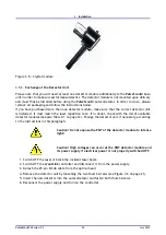
Figure 3.5.: Crystal module
3.5.2.
Exchange of the Detector Unit
Please note that you will need at least one detector module additionally to the
Pulse
Scout2
base
unit in order to make successful measurements. The detector module is not mounted upon delivery
and must thus be installed before using the
Pulse
Scout2
autocorrelator. In order to do so, please
remove all packaging and follow the instructions below.
If you have purchased more than one detector module, make sure that the correct detector unit
is installed. It must match the laser repetition rate. If in doubt, check with the list of available
detector modules (See also Table 2.1 on page 12). Change the detector unit, if necessary, according
to the instructions in this paragraph.
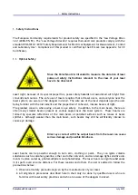
Caution! Do not expose the PMT of the detector module to intense
light!
Caution! High voltages can occur at the PMT detector module and
its power supply if electrical power is not properly switched OFF.
1. Switch OFF the laser or block the incident laser beam.
2. Switch OFF the
scout
Link
controller and disconnect it from the power supply.
3. Detach the 25-pin D-Sub cable from the optical head
4. Remove the detector unit by loosening the two thumb screws (see Figure 3.6 on page 21).
5. Insert the new detector into the autocorrelator and fasten both thumb screws.
6. Reconnect the power supply and turn on the controller.
Pulse
Scout2 Version 1.1
20
July 2015


