Chapter 2 Hardware Setup
20
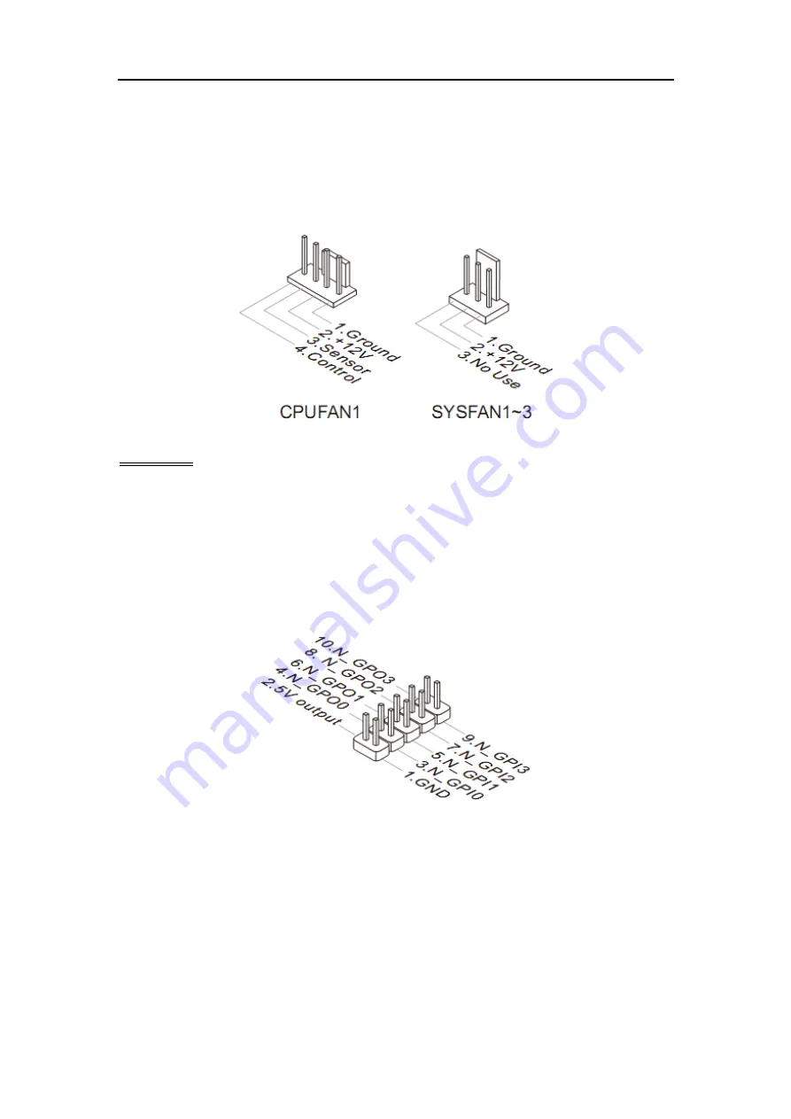
connecting the wire to the connectors, always note that the red wire is the
positive and should be connected to the +12V; the black wire is Ground and
should be connected to GND. If the mainboard has a System Hardware
Monitor chipset onboard, you must use a specially designed fan with speed
sensor to take advantage of the CPU fan control.
Important
Please refer to the recommended CPU fans at processor’s official website or
consult the vendors for proper CPU cooling fan.
GPIO Pin-header: JGPIO1
This connector is provided for the General-Purpose Input / Output (GPIO)
peripheral module.
Front Panel Pin-header: JFP1
This front panel connector is provided for electrical connection to the front
panel switches & LEDs and is compliant with Intel Front Panel I/O
Connectivity Design Guide.


