Troubleshooting
36
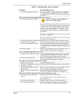
• The CPU PCB is defective.
Replace the CPU PCB with a known good PCB. See
PCB or Display PCB Replacement
The display backlight does not come on when the
Backlight
button is pressed.
• The
Backlight
bottom on the front
panel keypad is defective.
Caution: Unlock J3 before attempting to
remove flex circuit conductor.
Open the NPB-40, disconnect the front case from J3 on the
CPU PCB and connect an ohmmeter lead to the flex circuit
conductor for J3, pin 3 and individually connect the other
ohmmeter lead to each conductor for the buttons. Refer to
the front panel schematic diagram (**). Observe a short
when the button is pressed and an open when the button is
not pressed.
If incorrect, replace the front case. See
If correct, replace the CPU PCB. See
• Flex circuit between the front panel and
the CPU PCB is disconnected.
Inspect the flex circuit and reconnect if the flex circuit is
loose. See
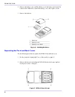
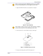
Separating the Front and Back Cases
• A CPU PCB Component has failed.
Inspect the CPU PCB components and circuit board for
cracking, burning, or damage and replace the CPU PCB if
CPU PCB or Display PCB Replacement
• CPU PC has failed.
Replace the CPU PCB with a known good PCB. See
PCB or Display PCB Replacement
• The
Backlight
LEDs on the Display
PCB have failed.
Replace the Display PCB with a known good PCB. See
CPU PCB or Display PCB Replacement
The NPB-40 shuts off when the
Backlight
button is pressed.
• The batteries are at or near a voltage too
low for the NPB-40 to operate.
Install new batteries. See the NPB-40 Operator’s manual.
The printer does not print.
• The printer and the NPB-40 are not
properly aligned.
Align the printer and the NPB-40. See the NPB40
Operator’s manual.
• The printer is turned off.
Turn the printer on. See the printer documentation.
• The
Data
bottom on the front panel
keypad is defective.
Caution: Unlock J3 before attempting to
remove flex circuit conductor.
Open the NPB-40, disconnect the front case from J3 on the
CPU PCB and connect an ohmmeter lead to the flex circuit
conductor for J3, pin 3 and individually connect the other
ohmmeter lead to each conductor for the buttons. Refer to
the front panel schematic diagram (**). Observe a short
when the button is pressed and an open when the button is
not pressed.
If incorrect, replace the front case. See
If correct, replace the CPU PCB. See
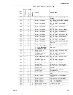
Table 3:
Troubleshooting Guide
(Continued)
Condition
Recommended Actione
Summary of Contents for Oximax NPB-40
Page 1: ......
Page 5: ...Contents NPB 40 iii Power Supply 81 Power Supply Monitoring 81 Index 103...
Page 8: ...Tables vi This Page Intentionally Blank...
Page 18: ...Introduction 10 This Page Intentionally Blank...
Page 22: ...Routine Maintenance 14 This Page Intentionally Blank...
Page 40: ...Performance Verification 32 This Page Intentionally Blank...
Page 50: ...Troubleshooting 42 This Page Intentionally Blank...
Page 66: ...Spare Parts 58 This Page Intentionally Blank...
Page 70: ...Packing for Shipment 62 This Page Intentionally Blank...
Page 82: ...Specifications 74 This Page Intentionally Blank...
Page 90: ...Technical Discussion 82 This Page Intentionally Blank...
Page 92: ...Technical Discussion 84 This Page Intentionally Blank...
Page 94: ...Technical Discussion 86 This Page Intentionally Blank...
Page 96: ...Technical Discussion 88 This Page Intentionally Blank...
Page 98: ...Technical Discussion 90 This Page Intentionally Blank...
Page 100: ...Technical Discussion 92 This Page Intentionally Blank...
Page 102: ...Technical Discussion 94 This Page Intentionally Blank...
Page 104: ...Technical Discussion 96 This Page Intentionally Blank...
Page 106: ...Technical Discussion 98 This Page Intentionally Blank...
Page 108: ...Technical Discussion 100 This Page Intentionally Blank...
Page 110: ...Technical Discussion 102 This Page Intentionally Blank...
Page 113: ......

