Disassembly Guide
NPB-40
47
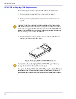
4. Separate the display PCB from the CPU PCB. See Figure 9.
Figure 9: Separating the Display PCB and CPU PCB
5. Place the defective PCB to the side.
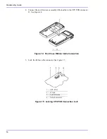
6. Align the new PCB (J1 and J2) and the removed good PCB (J1 and J2) and
gently press them together. See Figure 10.
Figure 10: Connecting PCBs
1 — J1
2 — Display PCB
3 — J2
4 — CPU PCB
1 — J1
2 — Display PCB
3 — J2
4 — CPU PCB
Summary of Contents for Oximax NPB-40
Page 1: ......
Page 5: ...Contents NPB 40 iii Power Supply 81 Power Supply Monitoring 81 Index 103...
Page 8: ...Tables vi This Page Intentionally Blank...
Page 18: ...Introduction 10 This Page Intentionally Blank...
Page 22: ...Routine Maintenance 14 This Page Intentionally Blank...
Page 40: ...Performance Verification 32 This Page Intentionally Blank...
Page 50: ...Troubleshooting 42 This Page Intentionally Blank...
Page 66: ...Spare Parts 58 This Page Intentionally Blank...
Page 70: ...Packing for Shipment 62 This Page Intentionally Blank...
Page 82: ...Specifications 74 This Page Intentionally Blank...
Page 90: ...Technical Discussion 82 This Page Intentionally Blank...
Page 92: ...Technical Discussion 84 This Page Intentionally Blank...
Page 94: ...Technical Discussion 86 This Page Intentionally Blank...
Page 96: ...Technical Discussion 88 This Page Intentionally Blank...
Page 98: ...Technical Discussion 90 This Page Intentionally Blank...
Page 100: ...Technical Discussion 92 This Page Intentionally Blank...
Page 102: ...Technical Discussion 94 This Page Intentionally Blank...
Page 104: ...Technical Discussion 96 This Page Intentionally Blank...
Page 106: ...Technical Discussion 98 This Page Intentionally Blank...
Page 108: ...Technical Discussion 100 This Page Intentionally Blank...
Page 110: ...Technical Discussion 102 This Page Intentionally Blank...
Page 113: ......


