background image

Precautions

Please read this manual carefully before using your plasma
monitor and keep the manual handy for future reference.


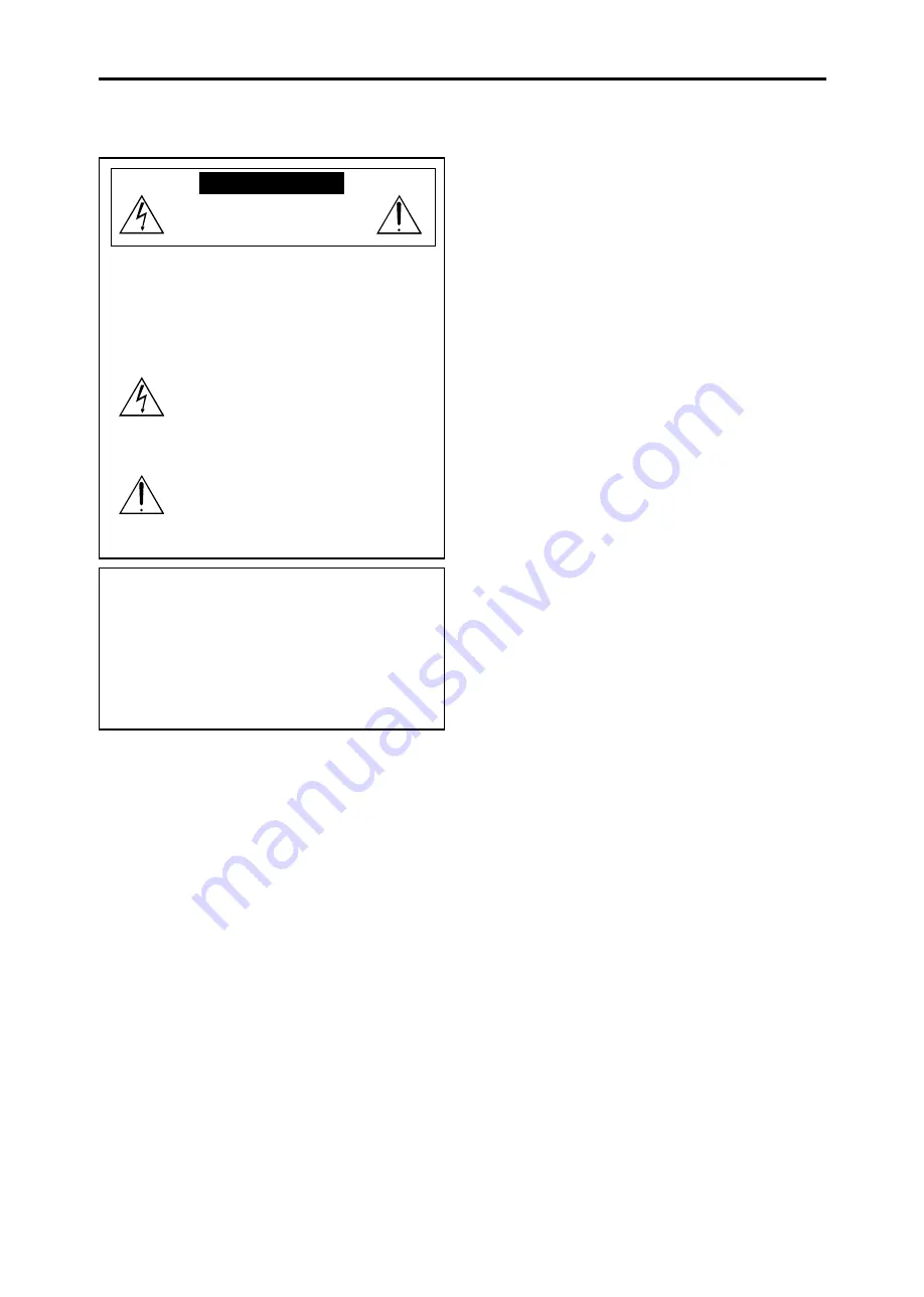
    CAUTION

RISK OF ELECTRIC SHOCK

DO NOT OPEN

CAUTION:  TO REDUCE THE RISK OF ELECTRIC

SHOCK, DO NOT REMOVE COVER. NO
USER-SERVICEABLE PARTS INSIDE.
REFER SERVICING TO QUALIFIED
SERVICE PERSONNEL.

This symbol warns the user that uninsulated
voltage within the unit may have sufficient
magnitude to cause electric shock.
Therefore, it is dangerous to make any kind
of contact with any part inside of this unit.

This symbol alerts the user that important
literature concerning the operation and
maintenance of this unit has been included.
Therefore, it should be read carefully in
order to avoid any problems.

WARNING

TO PREVENT FIRE OR SHOCK HAZARDS, DO NOT EXPOSE
THIS UNIT TO RAIN OR MOISTURE. ALSO DO NOT USE
THIS UNIT’S POLARIZED PLUG WITH AN EXTENSION CORD
RECEPTACLE OR OTHER OUTLETS, UNLESS THE
PRONGS CAN BE FULLY INSERTED. REFRAIN FROM
OPENING THE CABINET AS THERE ARE HIGH-VOLTAGE
COMPONENTS INSIDE. REFER SERVICING TO QUALIFIED
SERVICE PERSONNEL.

Warnings and Safety Precaution

This plasma monitor is designed and
manufactured to provide long, trouble-free service.
No maintenance other than cleaning is required.
Please see the section “Plasma monitor cleaning
procedure” on the next page.
The plasma display panel consists of fine picture
elements (cells) with more than 99.99 percent active
cells. There may be some cells that do not produce
light or remain lit.
For operating safety and to avoid damage to the unit,
read carefully and observe the following instructions.
To avoid shock and fire hazards:

1. Provide adequate space for ventilation to avoid internal

heat build-up. Do not cover rear vents or install the unit
in a closed cabinet or shelves.
 If you install the unit in an enclosure, make sure there
is adequate space at the top of the unit to allow hot air
to rise and escape. If the monitor becomes too hot, the
overheat protector will be activated and the monitor will
be turned off. If this happens, turn off the power to the
monitor and unplug the power cord. If the room where
the monitor is installed is particularly hot, move the
monitor to a cooler location, and wait for  60 minutes to
cool the monitor. If the problem persists, contact your
dealer for service.

2. Do not use this unit’s polarized plug with extension cords

or outlets unless the prongs can be completely inserted.

3. Do not expose the unit to water or moisture.
4. Avoid damage to the power cord, and do not attempt to

modify the power cord.

5. Unplug the power cord during electrical storms or if

the unit will not be used over a long period.

6. Do not open the cabinet which has potentially dangerous

high voltage components inside. If the unit is damaged in
this way the warranty will be void. Moreover, there is a
serious risk of electric shock.

7. Do not attempt to service or repair the unit. The

manufacturer is not liable for any bodily harm or damage
caused if unqualified persons attempt service or open
the back cover. Refer all service to authorized Service
Centers.

To avoid damage and prolong operating life:

1. Use only with 100-240V 50/60Hz AC power supply.

Continued operation at line voltages greater than 100-
240 Volts AC will shorten the life of the unit, and might
even cause a fire hazard.

2. Handle the unit carefully when installing it and do not

drop.

3. Set the unit away from heat, excessive dust, and direct

sunlight.

4. Protect the inside of the unit from liquids and small

metal objects. In case of accident, unplug the power
cord and have it serviced by an authorized Service
Center.

5. Do not hit or scratch the panel surface as this causes

flaws on the surface of the screen.

6. For correct installation and mounting it is strongly

recommended to use a trained, authorized dealer.

7. As is the case with any phosphor-based display (like a

CRT monitor, for example) light output will gradually
decrease over the life of a Plasma Display Panel.

8. To avoid sulfurization it is strongly recommended not to

place the unit in a dressing room in a public bath or hot
spring bath.

9. Do not use in a moving vehicle, as the unit could drop or

topple over and cause injuries.

10. Do not place the unit on its side, upside-down or with the

screen facing up or down, to avoid combustion or electric
shock.

Plasma monitor cleaning procedure:

1. Use a soft dry cloth to clean the front panel and bezel

area. Never use solvents such as alcohol or thinner to
clean these surfaces.

2. Clean plasma ventilation areas with a vacuum cleaner

with a soft brush nozzle attachment.

3. To ensure proper ventilation, cleaning of the ventilation

areas must be carried out monthly. More frequent cleaning
may be necessary depending on the environment in which
the plasma monitor is installed.

Recommendations to avoid or minimize phosphor burn-in:

Like all phosphor-based display devices and all other gas
plasma displays, plasma monitors can be susceptible to
phosphor burn under certain circumstances. Certain
operating conditions, such as the continuous display of a
static image over a prolonged period of time, can result in
phosphor burn if proper precautions are not taken. To protect
your investment in this plasma monitor, please adhere to the
following guidelines and recommendations for minimizing
the occurrence of image burn:

Important Information

Summary of Contents for PlasmaSync PX-61XM3A

Page 1: ...PlasmaSync Plasma Monitor NEC Solutions America Inc Operation Manual Enhanced split screen Model For the specifications of your plasma monitor refer to Model Information...

Page 2: ...ord during electrical storms or if the unit will not be used over a long period 6 Do not open the cabinet which has potentially dangerous high voltage components inside If the unit is damaged in this...

Page 3: ...SI NE PAS UTILISER LA FICHE POLARISEE AVEC UN PROLONGATEUR OU UNE AUTRE PRISE DE COURANT SAUF SI CES LAMES PEUVENT ETRE INSEREES A FOND NE PAS OUVRIR LE COFFRET DES COMPOSANTS HAUTETENSION SETROUVENT...

Page 4: ...edecessurfaces 2 Nettoyer les prises d a ration du plasma en proc dant l aide d une brosse poils doux fix e un aspirateur 3 Pour garantir la bonne ventilation du moniteur nettoyer les prises d air tou...

Page 5: ...ng transmitted to RGB1 terminal 23 Setting a computer image to the correct RGB select screen 23 Setting high definition images to the suitable screen size 24 Setting the Input Skip 24 Resetting to the...

Page 6: ...the equipment or injury to the installer Product warranty does not cover damage caused by improper installation Use only the mounting kit or stand provided by manufacturer and listed under Options Dra...

Page 7: ...imaly 4 screen is rough standard with lower than 1024 768 60Hz signal A distribution amplifier is particularly recommended when using 9 screen and over video wall From the second monitor onward connec...

Page 8: ...trol within a distance of about 7 m 23ft from the front of the monitor s remote control sensor andathorizontalandverticalanglesofuptoapproximately 30 The remote control operation may not function if t...

Page 9: ...n the On Screen Menu OSM mode Front View MENU ENTER INPUTSELECT DOWN UP LEFT RIGHT EXIT VOLUME MENU ENTER INPUTSELECT DOWN UP LEFT RIGHT EXIT VOLUME 4 5 6 7 1 3 2 t LEFT and RIGHT Enlarges or reduces...

Page 10: ...Discs etc here This input can be set for use with an RGB or component source see page 23 G RGB1 mini D Sub 15pin Connect an analog RGB signal from a computer etc here This input can be used for Input...

Page 11: ...settings on the screen 4 OFF TIMER Activates the off timer for the unit 5 SIDE BY SIDE Press this button to show a couple of pictures in the side by side mode 6 PICTURE IN PICTURE Press this button t...

Page 12: ...agnifying glass A press of the ZOOM button will reduce the picture and return it to its original size To change the picture position Select the position with the buttons 2 Press the POINTER button to...

Page 13: ...rections at different ratios Use this for watching normal video programs 4 3 with a wide screen ZOOM size screen The picture is expanded in the horizontal and vertical direction maintaining the origin...

Page 14: ...are registered trademarks of IBM Inc of the United States Note Do not allow the displayed in 4 3 mode for an extended period This can cause a phosphor burn in Wide Screen Operation with Computer Sign...

Page 15: ...ending on the combination of input signals In the table below means Yes means No Split screen operations may not function depending on the type of the RGB signals VIDEO1 VIDEO2 VIDEO3 HD DVD1 HD DVD2...

Page 16: ...n also be used to change the selection Zooming up pictures 1 Press the SELECT FREEZE button to make the desired picture active 2 Use the POINTER button and the ZOOM button to enlage the picture For de...

Page 17: ...tton on the remote control to select a sub menu or item PICTURE 1 2 EXIT CONTRAST BRIGHTNESS SHARPNESS COLOR TINT PICTURE MODE NR NEXT PAGE NORMAL OFF SEL RETURN ADJ 4 Adjust the level or change the s...

Page 18: ...NPUT1 VIDEO 1 3 HD DVD 1 2 RGB 1 3 YES 22 AUDIO INPUT2 VIDEO 1 3 HD DVD 1 2 RGB 1 3 YES 22 AUDIO INPUT3 VIDEO 1 3 HD DVD 1 2 RGB 1 3 YES 22 Main menu Sub menu Sub menu 2 Sub menu 3 Sub menu 4 RESET RE...

Page 19: ...N YES 31 LOOP OUT OFF ON YES 31 ID NUMBER ALL 1 256 YES 31 VIDEO WALL DIVIDER OFF 1 4 9 YES 32 POSITION No 1 No 4 No 7 No 15 No 16 No 31 No 32 No 56 32 DISP MODE SPLIT BLANK YES 32 AUTO ID OFF ON YES...

Page 20: ...TURN ADJ PICTURE MODE THEAT 1 Information Types of picture modes THEAT 1 2 Set this mode when watching video in a dark room This mode provides darker finer pictures like the screen in movie theaters F...

Page 21: ...s darker as the number increases in the sequence of 1 2 3 4 Making the Low Tone adjustments This feature allows more detailed tone to be reproduced especially in the dark area Example Setting 2 Set AD...

Page 22: ...e switches as follows each time the or button is pressed NORMAL FULL The mode can also be switched by pressing the WIDE button on the remote control The settings on the IMAGEADJUST menu are not preset...

Page 23: ...mation BNC INPUT Settings RGB Use the 5BNC terminals for RGB input COMP Use the 3BNC terminals for component input OPTION1 1 4 EXIT OSM BNC INPUT D SUB INPUT RGB SELECT HD SELECT INPUT SKIP ALL RESET...

Page 24: ...of the signal scan and display all signals ON If no input signal is present skip that signal SETTING NOW will appear during the input search WIDE1 When an 852 dot 480 line signal with a horizontal fre...

Page 25: ...ment operating status Not activated Activated Description Horizontal and vertical synchronizing signals are present from the computer Horizontal and or vertical synchronizing signals are not sent from...

Page 26: ...erval of 1 5 minutes 1 horizontal dot or 1 vertical line per interval INVERSE Use this to set the inverse mode or to display a white screen Example Setting INVERSE to WHITE On INVERSE of LONG LIFE men...

Page 27: ...ot be set when the WORKING TIME is ON THE WORKINGTIME and WAITINGTIME can be set for up to 12 hours and 45 minutes in units of 3 minutes To select ON for the WORKING TIME Set the hours of the working...

Page 28: ...RETURN ADJ Setting CloseCaption Choose the closed caption mode that allows text to be superimposed on display Example Setting CLOSECAPTION to CC2 Set ADVANCED OSM to ON in the main menu 1 2 then perfo...

Page 29: ...0 A M On PROGRAM of TIMER menu select ON then press the MENU ENTER button The PROGRAM TIMER screen appears Adjust the items Each mode switches each time the ZOOM button is pressed PROGRAM TIMER EXIT D...

Page 30: ...or SUB for PICTURE IN PICTURE BTM LFT TOP LFT and LEFT or RIGHT for S BY S1 3 Only one signal is selected for SINGLE The two repeat timers run consecutively i e Timer1 Timer2 Timer1 Timer2 When both...

Page 31: ...the ID number for the remote control Example Setting 2 Press the ID SELECT button on the remote control The ID SELECT screen appears On ID NUMBER of ID SELECT menu select 2 ID SELECT POSITION 1 EXIT 2...

Page 32: ...lay 1 Display 2 Display 4 Display 3 OFF Disables Auto ID function DISP MODE Select the screen mode from between two options Splitting Blanking Example Setting BLANK On DISP MODE of VIDEO WALL menu sel...

Page 33: ...cted Example Adjusting the vertical position On VIDEOWALL menu select IMAGEADJUST then press the MENU ENTER button The IMAGE ADJUST screen appears On V POSITION of IMAGEADJUST menu adjust the position...

Page 34: ...ANCED OSM to ON in the main menu 1 2 then perform the following operations On ZOOM NAV of OPTION4 menu select S BY S OPTION4 4 4 EXIT PREVIOUS PAGE SUB P DETECT ZOOM NAV PIC FREEZE SEAMLESS SW SELECT1...

Page 35: ...ire image on the sub screen S BY S Will show the entire image on the sub screen of side by side mode BTM LFT TOP LFT Will show the entire image on the sub screen of picture in picture mode Displaying...

Page 36: ...etc On MAIN MENU select SOURCE INFORMATION then press the MENU ENTER button The SOURCE INFORMATION is displayed SOURCE INFORMATION EXIT H FREQ V FREQ H POLARITY V POLARITY MEMORY RESOLUTION 48 4KHZ 6...

Page 37: ...H 01H 01H 82H OFF DFH 80H 60H C1H 01H 02H 83H Note Contact your local dealer for a full list of the External Control Codes if needed 1 5 9 6 2 3 4 7 8 Communication Parameters 1 Communication system A...

Page 38: ...r or colors are weak Nothing appears on screen Part of picture is cut off or picture is not centered Image is too large or too small Picture is unstable POWER STANDBY indicator is lighted in red POWER...

Page 39: ...ial technical adjustments set up including adjustment of user controls These costs are the responsibility of the NEC Solutions dealer from whom the product was purchased 3 Shipping charges HOW YOU CAN...

Page 40: ...Printed on recycled paper Printed in Japan 7S801381 NEC Solutions America Inc 1250 N Arlington Heights Road Suite 400 Itasca Illinois 60143 1248...

Reviews: