5. Using On-Screen Menu
116
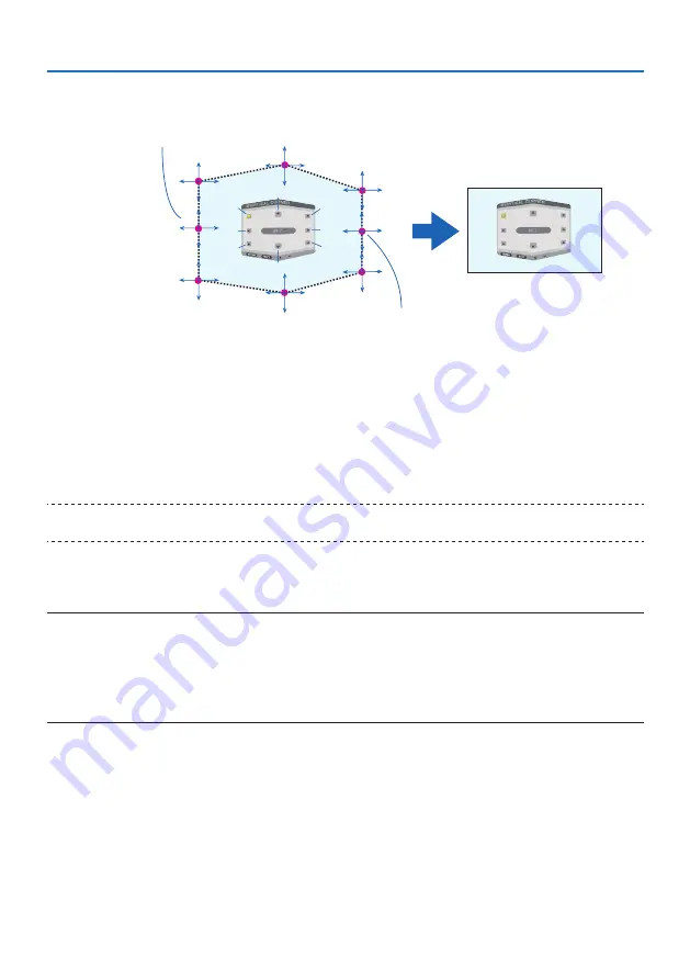
[Adjustment points of the [VERTICAL CORNER] screen and movement points of the projec-
tion screen]
a
a
b
b
c
c
d
d
e
e
f
f
g
g
h
h
Point d will be displaced in a parallel manner at the same time as Points a, d, f
Point e will be displaced in a parallel manner at the same time as Points f, g, h
4. Start from Step 2 onwards to adjust the other points.
5. When the adjustment is completed, press the
▼▲◀▶
buttons to align the cursor with the
[EXIT] in the adjustment screen and then press the ENTER button.
• Switch to the [GEOMETRIC CORRECTION] menu screen.
6. Press
◀
or
▶
button to move the cursor onto [OK] then press [ENTER].
• The adjusted values for [HORIZONTAL CORNER] or [VERTICAL CORNER] are stored and the
screen display goes back to the [GEOMETRIC CORRECTION].
TIP:
• A commercially available USB mouse is available to perform correction. (
→
page
)
WARP
Correct projected image distortion on a specific surface as a column or a sphere.
NOTE:
• When the maximum adjustment range is exceeded, distortion adjustment is disabled. Set up the projector at an optimal angle
since the more the adjustment volume gets large, the more image quality gets deterioration.
• Please note that the image will go out of focus due to the difference in the distance between peripheries and the center of the
screen for projections cutting across corners as on a column or a sphere. Lenses with short focal points are also not recommended
for projections cutting across corners as the image will go out of focus.
Summary of Contents for NP-PA1004UL-W
Page 236: ...NEC Display Solutions Ltd 2020...


