background image

66

Setting Up Your Projector and Chiller Unit

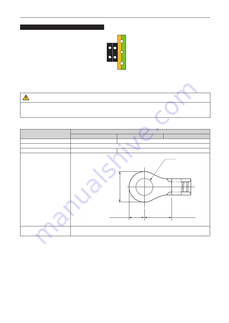
Compatible Cables and Solderless Terminals

Power terminal L, N

Ground terminal G

Solderless terminals and screw fastening torques compatible with the terminal block are specified below. This specifies the 
model name of the recommended solderless terminals. Use these parts or equivalent parts. If you are unable to use the recom-
mended solderless terminals, ensure that you use terminals of the dimensions shown in the following diagram. 

 CAUTION

Always use solderless terminals with the dimensions as shown in the following diagram. The use of parts with dimensions 
other than as designated creates a risk of the AC power supply unit short circuiting due to the terminal block generating 
heat and melting because the terminal block of the chiller unit cannot be attached correctly.

•  Power terminal (Black)

Item

Standards

IEC/EN

UL

CSA (C-UL)

Thickness of compatible wiring

2.0 mm

2

AWG14

Solderless terminal dimensions

M4

Tightening torque

1.3 N•m

1.0 N•m

Solderless terminal dimensions

Max. 3.3

Units: mm

φ

4.3

Max 6.8

Min. 6.3

Solderless terminal 
recommended part (J.S.T parts)

2

M4

J.S.T: J.S.T Manufacturing Co, Ltd. 

Summary of Contents for NC1700L

Page 1: ...Installation Manual DLP Cinema Projector NC1700L Chiller Unit NP 17CU01 DLP Cinema Projector Model No NP NC1700L ...

Page 2: ... applicable products for basic operation and remarks of the projector This document expects the readers who have basic knowledge about projector installation After reading please keep this document under care of the company which installed or adjusted the projector The product name used in this manual In this manual the device name is written as listed below If the function has difference by devic...

Page 3: ...MOISTURE CAUTION TO REDUCE THE RISK OF ELECTRIC SHOCK DO NOT OPEN COVER NO USER SERVICEABLE PARTS INSIDE REFER SERVICING TO QUALIFIED SERVICE PERSONNEL This symbol warns the user that uninsulated volt age within the unit may have sufficient magni tude to cause electric shock Therefore it is dan gerous to make any kind of contact with any part inside of this unit This symbol alerts the user that im...

Page 4: ...ese safety instructions are to ensure the long life of your projector and to prevent fire and shock Please read them carefully and heed all warnings Installation 1 Do not point the projection beam toward other people or reflective objects 2 Consult your dealer for information about transporting and installing the projector Do not attempt to transport and install the projector yourself The projecto...

Page 5: ...d power cable can cause electric shock or fire Do not bend or tug the power cable excessively Do not place the power cable under the projector or any heavy object Do not cover the power cable with other soft materials such as rugs Do not heat the power cable Do not change the arrangement of the installed power cable 4 If the projector will not be used for an extended period of time turn off the pr...

Page 6: ...lens paper to clean the lens and be careful not to scratch or mar the lens 5 Do not touch the projector or the power plug with wet hand Doing so can cause electrical shock or fire CAUTION 1 Do not unplug the power cable from the wall outlet or projector when the projector is powered on Doing so can damage the projector While projecting images While cooling after the projector has been turned off T...

Page 7: ...roduct EU wide legislation as implemented in each Member State requires that used electrical and electronic products carrying the mark left must be disposed of separately from nor mal household waste This includes projectors and their electrical accessories When you dispose of such prod ucts please follow the guidance of your local authority and or ask the shop where you pur chased the product Aft...

Page 8: ...s 1F Ire Building 2 Yangpyeong dong 4 ga Yeongdeungpo gu Seoul Korea 150 967 Telephone 82 2 2102 8591 Fax Line 82 2 2102 8600 Email Address moneybear hyosung com WEB Address http www hyosungitx com In Australia and New Zealand Company Name NEC Australia Pty Ltd Address 26 Rodborough Road Frenchs Forest NSW 2086 Telephone 131 632 from anywhere in Australia Email Address displays nec com au WEB Addr...

Page 9: ...d as RG3 of IEC62471 5 First edition 2015 Obey the laws and regulations of your country in relation to the installation and management of the device Internal laser output of the laser module Blue laser diodes Wave length 450 460 nm Output power 450 W Red laser diodes Wave length 636 642 nm Output power 100 W WARNING Always wear laser protection glasses that meet the following conditions while work...

Page 10: ...ion Label B Hazard Warning Symbol Explanatory Label Aperture Label Laser Aperture Class4 IEC60825 1 2nd edition Label B Risk Group Lamp Safety Label Label A Hazard Warning Symbol Explanatory Label and Aperture Label Label A ...

Page 11: ...11 Important Information Label C Label D Label E Label C Identification Label Label D Certification Statement Label Label E ...

Page 12: ... 22 Degree lens dependent Pulse duration CW Continuous Wave Modulation 23 192 Hz due to frame rate MPE Blue 450 460 nm Red 636 642 nm 260 J m2 NOHD 11 m Exposure duration 10 seconds NP 9LS12ZM1 Class 1 Class 2 Class 3R 0 1m 1 6m Tele 1 1m Wide 0 6m Tele 0 2m Wide Class 3B Class 4 Wide 0 15m Tele 0 1m Tele NP 9LS13ZM1 Class 1 Class 2 Class 3R 0 1m 2 5m Tele Wide Tele 0 2m Wide Class 3B Class 4 Wide...

Page 13: ...3B Class 4 Wide 0 25m Tele 1 8m 0 1m Tele NP 9LS16Z1 Class 1 Class 2 Class 3R Tele 2 55m Wide 1 0m Tele 0 65m Wide Class 3B Class 4 0 1m Wide 0 15m 0 15m Tele 2 6m 0 1m Wide Tele Class 1 Class 2 Class 3R NP 9LS20ZM1 0 2m 6 0m Tele 2 6m Wide 1 9m Tele 0 6m Wide Class 3B Class 4 0 1m 0 2m Wide 0 3m Tele Tele Wide ...

Page 14: ... Class 3R Tele Tele Wide Wide Class 3B Class 4 6 0m 3 8m 1 9m Tele 0 3m 0 3m 0 9m Wide 0 3m 0 3m Tele Wide NP 9LS40ZM1 NP 9LS40Z Class 1 Class 2 Class 3R Tele Wide 1 6m Wide Class 3B Class 4 7 5m 9 0m 0 35m Wide 0 35m Tele 3 5m Tele 0 3m Wide 0 3m Tele ...

Page 15: ...ree Degree Lens Zoom Lens Zoom Tele Wide Tele Wide NP 9LS12ZM1 15 7 22 1 NP 9LS12ZM1 8 5 12 2 NP 9LS13ZM1 13 3 20 2 NP 9LS13ZM1 7 1 11 0 NP 9LS16ZM1 10 1 16 6 NP 9LS16ZM1 5 4 9 0 NP 9LS16Z1 13 5 16 9 NP 9LS16Z1 7 1 9 1 NP 9LS20ZM1 7 2 13 2 NP 9LS20ZM1 3 8 7 1 NP 9LS20Z1 10 1 13 2 NP 9LS20Z1 5 4 7 1 NP 9LS40ZM1 NP 9LS40Z1 4 4 6 8 NP 9LS40ZM1 NP 9LS40Z1 2 3 3 6 H V V H ...

Page 16: ...e barrier installation position keep horizontal safety zone over 1 5m from the RG3 area In case to install the projector over head keep over 3m distance at least between the floor surface and the RG3 area Lens HD m H m V m NP 9LS12ZM1 2 8 1 63 0 86 NP 9LS13ZM1 3 5 1 67 0 88 NP 9LS16ZM1 4 2 1 56 0 82 NP 9LS16Z1 3 7 1 81 0 96 NP 9LS20ZM1 4 7 1 21 0 64 NP 9LS20Z1 5 2 1 91 1 01 NP 9LS40Z NP 9LS40ZM1 1...

Page 17: ...k the validity of taken security measures if appropriate safety zone based on the installed lens is secured Periodi cally check the validity and keep these results Educate the administrator of the projector operators about safety before starting to operate the projector To use the projector Instruct the administrator of the projector operators to perform inspections before powering on the projecto...

Page 18: ...eep over 2 5m distance at least between the floor surface and the area exceed ing the MPE values Avoid eyes or skin from exposing to direct or scattered emission exceeding the MPE values Lens Zoom HD m H m V m NP 9LS12ZM1 Wide 0 40 0 33 0 18 Tele 0 80 0 47 0 25 NP 9LS13ZM1 Wide 0 35 0 26 0 14 Tele 0 90 0 43 0 23 NP 9LS16ZM1 Wide 0 50 0 31 0 16 Tele 1 87 0 69 0 37 NP 9LS16Z1 Wide 1 00 0 61 0 32 Tel...

Page 19: ...riodi cally check the validity and keep these results Educate the administrator of the projector operators about safety before starting to operate the projector The education training examination and access control etc should be taken place according to ANSI Z 136 1 the latest version Clearly indicate signs of LASER RADIATION WARNING ACCESS LIMIT and No direct exposure to beam shall be permitted a...

Page 20: ...er halb des gerätes unisolierte teile vorhanden sind die hochspannung führen und deren berührung einen elektrischen schlag verursachen kann Dieses symbol macht den bëdiener darauf aufmerk sam dass wichtige den betrieb und die wartung des gerätes betreffende schriften beigefügt sind um irgendwelche probleme zu vermeiden sollten diese beschreibungen sorgfältig gelesen werden Vorsichtsmaßnahmen zur L...

Page 21: ...ierten Technikern installiert werden 3 Stellen Sie den Projektor auf eine flache waagerechte Fläche in einer trockenen Umgebung frei von Staub und Feuchtigkeit 4 Stellen Sie den Projektor weder in direktes Sonnenlicht noch in die Nähe einer Heizung oder sonstiger Hitze abstrahlender Einrichtungen 5 Wenn das Gerät direktem Sonnenlicht Rauch oder Dampf ausgesetzt wird können interne Komponenten besc...

Page 22: ...om 10 3A 60Hz Einphasenstrom Stellen Sie sicher dass die vorhandene Spannungsver sorgung diesen Vorgaben entspricht bevor Sie versu chen Ihren Projektor zu betreiben 2 Es wird kein Netzkabel mit dem Projektor geliefert Fra gen Sie Ihren Händler welches Netzkabel auszuwählen und zu kaufen ist Verwenden Sie ein Netzkabel das die Normen und Netzspannung des Landes in dem der Pro jektor verwendet wird...

Page 23: ...olgen Wenn der Projektor fallengelassen oder das Gehäuse beschädigt wurde Wenn der Projektor eine eindeutige Leistungsverän derung aufweist die einer Wartung bedarf 4 Lichtkegel des Projektors fern Da das von der Linse pro jizierte Licht umfassend ist können alle abnormalen Gegenstände die in der Lage sind das aus der Linse austretende Licht umzulenken unvorhersehbare Ereig nisse wie z B einen Bra...

Page 24: ...kt ein Lichtmodul beste hend aus mehreren Laserdioden 2 Diese Laserdioden sind im Lichtmodul eingeschlossen Für die Leistung des Lichtmoduls ist keine Wartung erforderlich 3 Der Endbenutzer darf das Lichtmodul nicht austauschen 4 Wenden Sie sich an einen qualifizierten Händler wenn Sie das Lichtmodul austauschen wollen oder weitere Informationen benötigen Über den Modus Große Höhe Stellen Sie den ...

Page 25: ...inois 60143 U S A Telefon 1 800 836 0655 Fax Nummer 1 800 356 2415 E Mail Adresse pjtechsupport necdisplay com Web Adresse http www necdisplay com In China Firmenname NEC Solutions China Co Ltd Addresse Rm 1903 Shining Building 35 Xueyuan Rd Haidian District Beijing 100191 P R C Telefon 8610 4008 900 678 E Mail Adresse nec support nec cn In Hongkong und Taiwan Firmenname Strong Westrex Inc Adresse...

Page 26: ...1 von IEC60825 1 Dritte Auflage 2014 eingestuft Dieses Produkt ist als RG3 von IEC62471 5 Erste Ausgabe 2015 eingestuft Beachten Sie bei der Installation und de Handhabung des Geräts die zutreffenden Gesetze und Vorschriften Ihres Landes Interner Laserausgang des Lasermoduls Blaue Laserdioden Wellenlänge 450 460 nm Ausgangsleistung 450 W Rote Laserdiode Wellenlänge 636 642 nm Ausgangsleistung 100 ...

Page 27: ...27 Wichtige Informationen Aufkleber C Aufkleber D Aufkleber E Aufkleber C Aufkleber mit Hersteller ID Aufkleber D Aufkleber E ...

Page 28: ...auf dass sich bei der Installation der Abdeckung die horizontale Sicherheitszone mindestens 1 5 m vom RG3 Bereich entfernt befindet Falls der Projektor über Kopf installiert wird halten Sie einen Abstand von mindestens 3 m zwischen der Bodenfläche und dem RG3 Bereich ein Linse HD m H m V m NP 9LS12ZM1 2 8 1 63 0 86 NP 9LS13ZM1 3 5 1 67 0 88 NP 9LS16ZM1 4 2 1 56 0 82 NP 9LS16Z1 3 7 1 81 0 96 NP 9LS...

Page 29: ...ngehalten wurden wenn die entsprechende Sicherheitszone gemäß der installierten Linse eingestellt wird Prüfen Sie dies in regelmäßigen Abständen und dokumentieren Sie die Ergebnisse Weisen Sie den Administrator des Projektors Bediener in die Sicherheitsbestimmungen ein bevor dieser mit dem Betrieb des Projektors beginnt Verwendung des Projektors Weisen Sie den Administrator des Projektors Bediener...

Page 30: ... 57 2 5 1 Removing the lens 59 2 6 Mounting the Option Board 60 2 6 1 Make the option board usable 62 2 7 Connecting the Power Cable for the Chiller Unit 64 2 7 1 AC Power Work Specifications Chiller Unit 65 2 7 2 Connecting the AC Power Cable to the Chiller Unit 69 2 8 Connecting the Hoses for the Chiller Unit and Control Cable 71 2 8 1 Connecting the Hoses for the Chiller Unit 71 2 8 2 Connectin...

Page 31: ...3 4 3 4 Setup 95 4 3 5 Installation 99 4 3 6 Memory 103 4 4 Title Setup 104 4 4 1 Preset Button 104 4 5 Information 105 4 5 1 Light Output 105 4 5 2 Lens Type 105 4 5 3 Preset Button 105 4 5 4 Usage 106 4 5 5 Error Code 106 4 5 6 Version 107 4 5 7 IP Address 107 4 5 8 Setup Date 108 4 5 9 Option Status 108 5 Appendix 109 5 1 List of Registered Titles when shipped from the factory 109 5 2 Error Cod...

Page 32: ... happens the temperature inside the projector will rise too high causing the over temperature protector to automatically turn off the projectors power 1 1 1 Projector Example 1 If there are walls on both sides of the projector 50cm 19 7 or greater 30cm 12 or greater NOTE The drawing shows the proper clearance required for the front back and top of the projector Example 2 If there is a wall behind ...

Page 33: ...projector in a case or the like GP I O 3D RS 232 USB REMOTE LAN Lens Rack 70cm 27 6 or greater 1 1 2 Installation Conditions for the Chiller Unit Allow a clearance of 50 cm 19 7 or greater between the chiller unit and its surroundings 50cm 19 7 or greater 50cm 19 7 or greater 50cm 19 7 or greater 50cm 19 7 or greater ...

Page 34: ...r Projector and the Chiller Unit Avoid placing the projector and chiller unit in such a way in which any air inlet and any outlet of them face each other Air inlet Air inlet Air inlet Air outlet Air outlet Air outlet Air inlet ...

Page 35: ...d die Innentemperatur des Projektors zu stark erhöht was dazu führt dass der Überhitzungsschutz des Projektors diesen automatisch ausschaltet 1 2 1 Aufbau des Projektors Beispiel 1 Wenn sich Wände auf beiden Seiten des Projektors befinden 50 cm oder mehr 30 cm oder mehr HINWEIS Die Abbildung zeigt den ordnungsgemäßen Abstand für die Vorder Rück und Oberseite des Projektors Beispiel 2 Wenn sich ein...

Page 36: ...Sie das Gerät nicht in einen Behälter wenn Sie ein Gestell verwenden GP I O 3D RS 232 USB REMOTE LAN Linse Gestell mehr als 70 cm 1 2 2 Aufbau der Wasserkühleinheit Bitte lassen Sie im Umkreis von 50 cm um das Gerät einen Freiraum mehr als 50 cm mehr als 50 cm mehr als 50 cm mehr als 50 cm ...

Page 37: ...nd the Chiller Unit Achten Sie darauf dass sich Lufteinlass und Luftauslass der Wasserkühleinheit nicht gegenseitig stören wenn Sie den Projektor aufbauen Lufteinlass Lufteinlass Lufteinlass Luftauslass Luftauslass Luftauslass Lufteinlass ...

Page 38: ...zero degree In case of projection from an upper position or from the right or left it is necessary to calculate the width for the minimum projected image that is a little larger than the screen size Width of minimum Screen Projected image 1 3 1 Screen Type The following two types of screen masks can be used for the DLP Cinema Projector Check the screen mask for your projector for its type before s...

Page 39: ...39 Before Setting Up Your Projector and the Chiller Unit Vertical moving screen mask Screen masks move vertically to adjust the screen Screen Screen mask Screen mask ...

Page 40: ...n 3 Select the lens that satisfies the zoom magnification calculated in 1 and 2 SCOPE projection Lens magnification Length of projection L Screen width W VISTA FLAT HDTV projection Lens magnification Length of projection L Screen width W 2048 Number of pixels per horizontal line Note Number of pixels per horizontal line 1998 for VISTA FLAT 1920 for HDTV Select a lens that meets the magnification r...

Page 41: ...3 2 1 NP 9LS16ZM1 1 62 2 7 NP 9LS20ZM1 2 09 3 9 Examples of selecting the lens unit If the projection distance L 30 m the screen width W 15 m SCOPE projection 30m 2 0x 15m VISTA FLAT projection 30m 1 95x 15m 2048 1998 HDTV projection 30m 1 88x 15m 2048 1920 Therefore the following lens units which satisfy the magnifications in all of the above projections are selected Not using the lens memory fun...

Page 42: ...ould be carried by holding the handles on the base of the unit by 4 or more people WARNING When moving the projector first turn off the power and always disconnect the power plug from the electrical outlet and check that all of the connecting cables between equipment and the lenses have been removed Handles Handles ...

Page 43: ...ed on the LCD screen of the projector main unit Tamper Fail IMB Service Door Tamper When NP 90MS02 4K mounted Encrypted contents cannot be displayed while an error message is being displayed Refer to 3 2 Recovering from Tamper Errors page 79 for details on how to clear the error message Position of the key locks on the covers When removing or attaching a cover of the projector main unit the lock n...

Page 44: ...n attaching or removing lenses page 57 Top Cover Removing and attaching the cover is performed by a trained service engineer The lock should only be unlocked by service engineers Side Cover The lock is unlocked when attaching or removing the option board page 60 GP I O 3D RS 232 USB REMOTE LAN ...

Page 45: ...u do not return the lens position to the center the lens may interfere and prevent you from removing mounting the front cover Preparation Phillips head screwdriver No 2 and cover key attached goods 1 Remove the Air inlet cover Slide the Air inlet cover in the direction of the arrow to remove Handle 2 Loosen two screws securing the front cover until the Phillips screwdriver goes into a freewheeling...

Page 46: ...ont cover Hold the bottom left of the cover with your left hand and the base of the lens hood with your right hand and pull the cover directly towards you to remove it This completes removing the front cover To mount the cover perform the removal procedure in reverse Make sure that you do not forget to tighten the screw or to lock the key lock ...

Page 47: ... screwdriver No 2 and cover key attached goods 1 Loosen the four fixing screws on the side cover Loosen four screws on the side cover until they are free to spin The screws do not detach from the cover GP I O 3D RS 232 USB REMOTE LAN 2 Unlock the side cover Unlock the cover using the cover key GP I O 3D RS 232 USB REMOTE LAN ...

Page 48: ... towards you so that the tabs do not get bent 2 Using the bottom edge of the side cover as a pivot pull the top side of the cover towards you Since there are hooks at the bottom of the side cover take care to avoid applying too much force when tilting the cover Tilting the cover towards you will loosen the attachment between the hooks and the projector 3 Once the hooks have come loose remove the c...

Page 49: ...ing the Lens Unit See page 57 Step 4 Mounting the following optional parts as required Installing the Media Block NP 90MS02 4K See page 60 Chiller unit Step 1 Connecting the Power Cable for the Chiller Unit See page 64 Step 2 Connecting the Hoses for the Chiller Unit See page 71 Connecting the Control Cable See page 73 Step 3 Pouring the Coolant See page 74 Step 4 Setting the Chiller Unit See page...

Page 50: ... 35 mm at the maximum Rotate it counterclockwise for extension CAUTION Do not extend the adjuster by more than 35 mm Rotating it forcefully may cause the adjuster to come off or be damaged To adjust the level adjusters of the projector extend the two level adjusters at the front and the back at the same time so that the weight is imposed to them equally If you adjust only one adjuster the weight i...

Page 51: ...ble refer to the projector User s Manual Before connecting the power cables check that the main power switch of the projector is turned off Implement the con nection with AC power shut off Be sure to ground the equipment to ensure safety Use a power cable that meets the standards and power supply voltage of the country where you are using the projector page 52 and always connect the equipment to t...

Page 52: ...hat the connector meets the following current capacity specifications Power supply voltage Projector input current Power cable current capacity AC 200 240V 10 7A MAX 250V 16A or higher Furthermore use plugs cables and connectors that are suitable for the regulations of the country of installation as shown in the following table NOTE For users in North America Use a power cable no longer than 4 5m ...

Page 53: ...Chiller Unit China Plug Cable Connector GB2099 RVV 300 500 GB17465 1 Connector Dimensions of the connector of the power cable are shown below 7 0 5 0 28 0 0 9 20 0 0 7 6 0 0 5 0 2 5 0 5 0 2 5 0 5 0 8 0 2 13 0 2 Unit mm R3 5 min 20 min ...

Page 54: ...es Netzkabels siehe des Projektors Bedienungshandbuch Bevor Sie das Netzkabel anschließen prüfen Sie ob die Hauptstromschalter des Projektors ausgeschaltet ist Stellen Sie die Verbindungen bei ausgeschaltetem Netzstrom her Erden Sie das Gerät um die Sicherheit zu gewährleisten Verwenden Sie ein Netzkabel das die Normen und Netzspan nung des Landes in dem der Projektor verwendet wird erfüllt Seite ...

Page 55: ...C20 Eingang gemäß IEC60320 zum Anschließen des Netzkabels ausgestattet Verwenden Sie einen IEC60320 C19 kompatiblen Netzkabelanschluss und sorgen Sie dafür dass der Anschluss über die unten angegebene Stromkapazität verfügt Netzspannung Projektor Eingangsstrom Netzkabel Stromkapazität 200 240 V Wechselstrom 10 7 A MAX 250 V 16 A oder höher Verwenden Sie zudem Stecker Kabel und Steckverbinder die d...

Page 56: ...erbinder JIS C 8303 VCTF 3 x 2 0mm IEC 320 C19 China Stecker Kabel Steckverbinder GB2099 RVV 300 500 GB17465 1 Steckverbinder Die Abmessungen des Netzkabels sind unten angegeben 7 0 5 0 28 0 0 9 20 0 0 7 6 0 0 5 0 2 5 0 5 0 2 5 0 5 0 8 0 2 13 0 2 Einheit mm R3 5 Min 20 Min ...

Page 57: ...ront cover Turn off the power and wait for the cooling fan to stop and turn off the main power switch before mounting or removing the lens Never touch the lens surface while the projector is operating Be very careful not to let dirt grease etc on the lens surface and not to scratch the lens surface Perform these operations on a flat surface over a piece of cloth etc to prevent the lens from gettin...

Page 58: ...until it clicks to lock the lens unit into the projector 5 Mount the front cover to the projector This completes the installation of the lens NOTE Perform the following steps before adjusting the lens Common to all lens units Configure the lens type setting and select the lens type that matches the lens unit that is attached page 84 Lens units that support the lens memory function Execute lens cal...

Page 59: ...r page 45 1 Rotate the lens counterclockwise while holding down the RELEASE LEVER The lens unit can be removed from the projector RELEASE LEVER 2 Slowly remove the lens from the projector by pulling it straight out After removing the lens attach the lens cap to both the front and back of the lens for proper storage If the projector is stored without the lens attach the dust cover to the lens hood ...

Page 60: ...r a tamper event is detected by the tamper detection circuit When you start the projector after attaching the cover the following error message is displayed on the LCD screen of the projector main unit IMB Service Door Tamper If you remove the blocking panel or option board from a slot a tamper event is detected by the tamper detec tion circuit When you start the projector after attaching the cove...

Page 61: ...king panel Slot NOTE Carefully store the blocking panel and screws that you removed 3 Mount the option board to the projector 1 Insert the board by following the guide on either side of the slot 2 Tighten up the knurled screws 2 places until it fix guide left right 4 Mount the side cover to the projector This completes the mounting of option board Next recover the tamper error For the procedure of...

Page 62: ...r in standby mode 2 Enable the service personnel menu These settings are for our service personnel and cannot normally user mode be used You need to enter a passcode to enable the service personnel menu Refer to the 4 1 1 When You Use the Service Personnel Menu page 90 for the procedure 3 Press the MENU button on the control panel Title Select is displayed in the menu From this procedure on contro...

Page 63: ...9 Press the EXIT button several times The projector exits the menu and goes back to the regular screen If you press the EXIT button and then select Yes and press the ENTER button on a regular screen you will returned to user mode This completes the setting of the projector TIP Settings of slot can be confirmed at projector s Information Option Status ...

Page 64: ...due to fire or electric shock CAUTION When conducting the power work to connect the power cable make sure that the main power switch to the projector and the chiller unit are turned off and that the AC power supply has been disconnected Contact a certified professional to perform the power work from the building power facilities to the installation location for the projector and the chiller unit T...

Page 65: ...the Europe market any one type of the following wire shall be used for assembly H05VV F 60227 IEC 53 H05V2V2 F 60227 IEC 57 H05RR F 60245 IEC 53 H05RN F 60245 IEC 57 Use a round type UL listed solderless terminal for the section connected to the chiller unit In addition when clamping this terminal with the cable use an UL listed tool Refer to Compatible Cables and Solderless Terminals page 66 on t...

Page 66: ...iagram CAUTION Always use solderless terminals with the dimensions as shown in the following diagram The use of parts with dimensions other than as designated creates a risk of the AC power supply unit short circuiting due to the terminal block generating heat and melting because the terminal block of the chiller unit cannot be attached correctly Power terminal Black Item Standards IEC EN UL CSA C...

Page 67: ... IEC EN UL CSA C UL Thickness of compatible wiring 2 0 mm2 AWG14 Solderless terminal dimensions M3 Tightening torque 0 6 to 0 8 N m Solderless terminal dimensions Units mm Max 3 3 Min φ3 7 Max 6 8 Min 6 3 Solderless terminal recommended part J S T parts 2 M3 J S T J S T Manufacturing Co Ltd ...

Page 68: ...h the sleeves after tightening the screw Tighten the fixing screw to the designated torque Use sleeves and secure the insulation to ensure that terminals do not touch each other If the cables are attached to the power supply terminal without using sleeves there is a risk of the terminals touching each other as shown in the photograph on the right When connecting the cables to the ground terminal b...

Page 69: ...h the cable holes Fit the power cable through the cable holes When the cable is too thick replace the holding clip for AC power cable with that included in the accessories 3 Insert the L N wire of the AC power cable into the connecting terminal and tighten the screws Insert the AC power cable crimp terminals over the connecting terminal securement holes and tighten the screws with a Phillips head ...

Page 70: ...ecting terminal WARNING Firmly tighten the ground cable to the connecting terminal After tightening all screws check that all power cables are properly tightened and in place If the screws are not firmly tightened this may cause serious personal injury or even death 6 Return the arm in the reverse procedure screw the ground terminal Return the arm and tighten the screw of the ground terminal with ...

Page 71: ...y cause fatal serious or other bodily injuries due to fire or electric shock CAUTION Before connecting the Hoses for the Chiller Unit and Control Cable check that the main power switch of the projector and the chiller unit is turned off Implement the connection with AC power shut off 2 8 1 Connecting the Hoses for the Chiller Unit 1 Connect the hose attachment port OUT on the projector and the coo...

Page 72: ... with a hose for the chiller unit supplied as an accessory Securely insert the hose all the way in To disconnect the hose push the button at each end of the hose and pull out the hose Hose attachment port OUT Hose attachment port IN Hose for the Chiller Unit Button Button CAUTION Incorrect connection of the hose may shorten the use period of the laser module ...

Page 73: ...e unit from the projector connect the control cable 1 Connect the chiller unit control port RJ 45 on the projector and the connector for communica tion line RJ 45 on the chiller unit with the control cable supplied as an accessory GP I O 3D RS 232 USB REMOTE LAN Chiller unit control port RJ 45 Connector for communication line RJ 45 Control cable ...

Page 74: ...enishing the coolant thoroughly before using it so that no impurity is mixed in the coolant Tighten the cap for the filler inlet for coolant by hand Excessively tightening the cap using a tool may damage the filler inlet for coolant or cap The coolant replacement period of the water cooling machine is 3 years Please periodically replace In case of unopened coolant is kept for 3 years Please open t...

Page 75: ...ead screwdriver and remove the cover Pull out the drain port Cover 2 Place a container for receiving the coolant under the drain port Amount of coolant About 12 liters at maximum 3 Open the valve of the drain port and drain the coolant in the tank Valve 4 Close the valve of the drain port 5 Put the drain port back in place and mount the cover by reversing the procedure for removing it ...

Page 76: ... setting items 2 sp display Shows the SP value set temperature etc or the set value of each setting item 3 Mode indicators rdy Lights in READY mode control stop man Lights in MANUAL mode manual operation mode ev1 ev3 Lights when event relay output is ON otl ot2 Lights when control output is ON 4 Adjustment key Press the key for more than 5 seconds and change the value displayed on the sp display w...

Page 77: ...each error code E02 Chiller unit pump motor error E03 Chiller unit pump compressor error E04 Coolant pressure too high Coolant is higher E06 Low coolant pressure E07 Coolant flow rate error E08 Heat sink system error 2 10 2 Fixing the Chiller Unit After placing the chiller unit at a desired installation location see page 33 push the knob of each caster and lock the caster to fix the chiller unit T...

Page 78: ...justing the Lens See page 84 Display the test pattern to adjust the screen size screen angle and focus Step5 Connecting with the Image Input Port See page 87 Step6 Connecting the Various Control Terminal See page 88 This chapter explains the adjustment and connection of the projector with Steps 1 to 6 Steps 1 to 6 complete the adjustment and connection of the projector Next carry out various setti...

Page 79: ...on circuit Action Error code Error message Cover removed Front cover Side cover 586 IMB Service Door Tamper Slot device or blocking panel removed Blocking panel Media block 582 584 582 IMB Physical Marriage Tamper 584 IMB Marriage NOT Active TIP Error codes can be checked when using the DCC While the above error messages are being displayed encrypted contents cannot be displayed Refer to 3 2 1 Cle...

Page 80: ...vents using the following procedure Start clearing the tamper events Finish clearing the tamper events Error codes 582 and 584 have occurred Error code 586 has occurred Have the tamper events been cleared Step 2 Perform re marriage using the Digital Cinema Communicator Step 1 Clear the Service Door Tamper by using the buttons on the Control Panel Turn off the projector main unit disconnect the AC ...

Page 81: ...tributor Always store the password remote controller and projector in a safe place and never divulge the password to unauthorized entities Entered password is indicated with on the LCD In case entered password characters are indicated on the LCD it is machine trouble Consult with the distributor Step 2 Perform Re Marriage using the Digital Cinema Communicator DCC is used to perform re marriage Ref...

Page 82: ...n unless the administrator key is inserted 4 Turn on the main power switch on the side of the projector A buzzer will ring on the projector The POWER button indicator will blink green and the SYSTEM status indicator will light orange standby state KEY LOCK becomes automatically on if no control panel operation takes place in the standby state for 30 seconds by default Buttons on the control panel ...

Page 83: ...press the DOWN button 6 Check that Image Orient is properly selected and press the DOWN button If Image Orient is not properly selected press the LEFT RIGHT buttons to select it 7 Press the LEFT RIGHT buttons to select the projection method When shipped from the factory it is set to Normal F Normal F Front projection With the projector installed on the pedestal projection is executed from the fron...

Page 84: ...d in the menu 2 Press the LEFT RIGHT button to display Configuration and press the DOWN button 3 Press the LEFT RIGHT button to display Installation and press the DOWN button 4 Press the LEFT RIGHT button to display Lens Type and press the DOWN button 5 Press the LEFT RIGHT button to select the type of lens attached to the projector When shipped from the factory it is set to Without Sensor Without...

Page 85: ...llation and press the DOWN button 4 Press the LEFT RIGHT button to display Lens Calibrate and press the DOWN button 5 Check that Execute is displayed and press the ENTER button The confirmation screen will appear 6 Select Yes in the confirmation screen and then press the ENTER button Carry out calibration in the order of focus lens and zoom lens 3 6 3 Display the Test Pattern 1 Press the MENU butt...

Page 86: ...HT buttons to roughly adjust the screen angle so that the screen height and the image height are the same 2 Press the UP DOWN buttons to roughly adjust the focus 3 Adjust the surface on which the projector is set up and the level adjuster of the projector to adjust the setup position height and tile front back and left right of the projector so that the projected image is level at the screen cente...

Page 87: ...d to option board is listed below For the connection diagram of projector and peripheral equipment refer to Installation manual of option board Option Board Image Input Port NP 90MS02 4K Note HDMI input port x1 SDI input port x2 Note The NP 90MS02 4K video input ports do not support CineLink 2 The NP 90MS02 4K video input ports cannot display the encrypted contents ...

Page 88: ...ma server Use a retail LAN cable 10 100 1000Base T for the connection between the projector and the computer after checking with your network administrator Chiller unit control port Use this port to control the chiller unit from the projector through a LAN connection Use a retail Control cable 10 100 1000Base T for the connection between the projector and the computer after checking with your netw...

Page 89: ...has been used 95 Setup Douser Setup Sets the douser open close state 95 Panel Key Lock Locks the buttons on the projector s control panel so that they cannot be operated 96 Auto Key Lock Enables or disables Auto Key Lock 96 3D Connector Sets the signal input terminal for a 3D image system 3D terminal or GPI O terminal Sets the video input port for 3D video systems 96 Off Timer Sets the time until ...

Page 90: ...r privileges 4 1 1 When You Use the Service Personnel Menu To use the menu for service personnel you need to input the passcode This section describes how to display the passcode entry screen and how to enter the passcode Refer to the Projector Manual for details on how to enter text 1 Press the MENU button for three seconds or longer The passcode input screen will be displayed on the LCD screen a...

Page 91: ...he projector s control panel and call them up directly using those buttons See page 104 Displays the currently selected item with asterisk Selects the title to be projected 4 2 2 Test Pattern Selects the test pattern to be projected Displays the currently selected item with asterisk Selects the test pattern to be projected OFF Alignment Cross Hatch Convergence Red Green Blue White Black White 50 I...

Page 92: ...reen Press the ENTER button to switch the display between Lens Position and Focus Zoom adjustments Press the EXIT button to return to a menu one level above Lens Position Adjusts the position of the projected screen The projected screen moves in the selected direction as you press the UP DOWN LEFT RIGHT button Focus Zoom Adjusts the size Zoom and focus Focus of the projected screen Press the UP DO...

Page 93: ...d preset buttons and title settings Network settings All adjustment and setting values Select the item to be reset Press the ENTER button to execute resetting P Button Title Resets the allocation of preset buttons and all registered titles LAN Resets the network settings All Resets all adjustment and setting values NOTE If you are logged in to the projector with Installation privileges you cannot ...

Page 94: ...the Phosphor usage time Press the ENTER button then select Yes in the displayed confirmation screen and then press the ENTER button to reset the Phosphor usage time Press the ENTER button to display the confirmation screen Diffuser Reset the Diffuser usage time Press the ENTER button then select Yes in the displayed confirmation screen and then press the ENTER button to reset the Diffuser usage ti...

Page 95: ...umber of times the douser has been used Press the ENTER button to display the confirmation screen 4 3 4 Setup This menu is for service personnel For the procedure to use it refer to 4 1 1 When You Use the Service Personnel Menu page 90 Douser Setup Sets the douser open close state Request your dealer distributor to perform the setting Selects the item Displays the currently selected item with aste...

Page 96: ...nit control panel for 30 seconds after entering the standby state If you do not perform any operations for 30 seconds after releasing the key lock the key lock is applied again Disable Disables the auto key lock function Although the key lock becomes active after entering the standby state once you release the key lock it is not automatically applied 3D Connector Selects the port for 3D video syst...

Page 97: ...e format Left H Set to No Preset to stop the timer Displays the remaining time until the power is turned off Sets the time until the power is turned off No Preset Timer off Message Sets the time until the replacement cycle units hours of a part such as the light source Once the usage time of the part exceeds the configured time a message is displayed on the LCD screen 0 H is set by default With th...

Page 98: ...t up Buzzer Sets whether to use or not use the buzzer Enable Use Disable Not use the buzzer does not sound Control Button Sets whether to use or not use the indicators on the projector s control panel Enable Use Disable Not use the LED next to the buttons do not light up LCD Backlight Sets whether to use or not use the illumination and LCD screen backlight on the projector s control panel Enable U...

Page 99: ...TER button to display the menu Image Orient Set the projection method FanTiltSetting Note Set the cooling method to match the projection method Note Upgrade function If you selected Image Orient Displays the currently selected item with asterisk Displays the setting Normal F Front projection With the projector installed on the pedestal projection is executed from the front of the screen Normal R R...

Page 100: ... lenses that support the lens memory function Once you have attached a lens that supports the lens memory function always execute calibration This menu item is available only when the projector power is turned on and you are logged into the projector with Advanced User or higher privileges NOTE This items cannot be used if Lens Type is set to Without Sensor Press the ENTER button to execute calibr...

Page 101: ...me Use this to set the date and time on the projector The internal clock in the projector uses coordinated universal time UTC This sets the time difference between the standard time in your region and UTC Displays the currently setting with asterisk Sets the time difference between the standard time in your region and UTC Press the ENTER button to check the time difference between the built in pro...

Page 102: ... to overheat and the protector could shut down If this happens wait a couple minutes and turn on the projector Using the projector at altitudes approximately 5500 feet 1600 meters or higher can shorten the life of internal parts Service Adj This is used during shadow adjustment and lens mount adjustment focus balance adjustment This menu item can only be used while in standby If you press the ENTE...

Page 103: ...the ENTER button The selected memory light memory or lens memory is overwritten with the current settings NOTE Lens memory and light memory cannot be newly registered Use DCC to register the lens memory and light memory in advance Refer to Digital Cinema Communicator for S2 Installation Manual for details registering the lens memory and light memory The lens memory function cannot be used when the...

Page 104: ...tle to another number cancel the assign ment once and then set it to any button again The Preset Button 1 to Preset Button 8 settings correspond to buttons 1 to 8 on the control panel To select the titles allocated to Preset Button 9 to Preset Button 16 press the 1 to 8 button while holding down the Up button on the control panel Select the preset button number 1 to 16 Display the selected number ...

Page 105: ...sor Using a lens unit that does not support the lens memory function With Sensor Using a lens unit that supports the lens memory function 4 5 3 Preset Button Displays the titles assigned to the preset buttons 1 to 8 buttons on the projector s control panel Selects the preset button number whose contents you want to display Displays the assigned title numbers Displays the registered names of the as...

Page 106: ...e diffuser and the value that is displayed is the amount of usage time remaining approximate Chiller Display of the usage time of Chiller unit and the value that is displayed is the amount of usage time remaining approximate Chiller Fan Displays the usage time of the Chiller unit fan Filter Cleaning Displays the usage time of the air filter Fan Usage Displays the usage time of the fan Douser Count...

Page 107: ...P ConfigFile FMT FPGA Slave BIOS Slave Firmware Opt MCU Secure Processor Lens Laser Driver IMB Displays the vendor name and version information about the media block IMB When the projector is in standby mode the vendor name is blank and the version information displays Not Use when IMB is not mounted to the projector Displays the vendor name Displays the version information 4 5 7 IP Address Displa...

Page 108: ...details Displays the date when the projector was set up starting date of the warranty period 4 5 9 Option Status Displays the link status of the device mounted in slot on the projector The device name is displayed in when the projector is in standby or when connection to the device cannot be confirmed Displays the link status of the device in slot NP 90MS NP 90MS02 4K Vendor Name IMB Media block N...

Page 109: ...ze HxV Aspect Ratio SAME FILE NAME Tolerance Box White Clip 1 001 IMS Auto IMB DCDM_XYZ_Auto 0x0 0 DC28_DCI_XYZE_314_351 Not Use Use Disable 2048x1080 No Crop M10I OFF 2 002 IMS 2K 185 IMB DCDM_XYZ_185 1998x1080 0 DC28_DCI_XYZE_314_351 Not Use Use Disable 2048x1080 No Crop M10I OFF 3 003 IMS 2K 239 IMB DCDM_XYZ_239 2048x858 0 DC28_DCI_XYZE_314_351 Not Use Use Disable 2048x1080 No Crop M10I OFF ...

Page 110: ... busy This message would be shown on Log not on LCD 177 Tamper Fail Service door tamper switch of projector is open 178 Marriage Tamper Fail Marriage tamper switch of projector is open 190 The Validity has expired The time limit for use of the projector has expired In cases when the validity setting has been configured with the projector 191 Different Serial Number There is a mismtach in the seria...

Page 111: ...SB status error 348 Green DAD1000 Thermal Shutdown Error FSB status error 349 Blue Satellite Reports Reset FSB status error 350 Blue Satellite Serial Link Error ICP or FSB status error 351 Blue Satellite Firmware Configuration Error ICP or FSB status error 352 Blue DAD1000 Bias Under Voltage Error FSB status error 353 Blue DAD1000 Reset Under Voltage Error FSB status error 354 Blue DAD1000 Offset ...

Page 112: ...rnal abnormality 791 FanInitError Failed to initialize fans 792 ExGpioFail Failed to control the signal connecting to Ballast Slave board internal abnormality 800 Fan15 Stop Fan15 has stopped 801 Fan16 Stop Fan16 has stopped 802 Pump Stop Pump has stopped 804 PhosphorWheel Stop Phosphor Wheel has stopped 805 Diffuser1 Wheel Stop Diffuser1 Wheel has stopped 806 Fan17 Stop Fan17 has stopped 810 Fan1...

Page 113: ...550 EEPROM IC2800 Write Fail Verify I2C Device Access Error 2000 IntegrityFail Integrity error with the internal software code of the projector When this error has occurred the projector will not accept any external demands Communication with external devices will not be performed either 2010 Incorrect power off PowerOff was not performed correctly last time 2100 Diffuser2 Wheel Stop Diffuser2 Whe...

Page 114: ...pressor over loading Chiller Compressor is abnormal 2143 Chiller Refrigerant pressure too high Chiller Refrigerant pressure too high 2144 Chiller Coolant pressure too low Chiller Coolant pressure too low 2145 Chiller Refrigerant pressure too low Chiller Refrigerant pressure too low 2146 Chiller Cooling liquid flowing error Chiller Cooling liquid flowing is abnormal 2147 Chiller Cooling Fan Error C...

Page 115: ...ttaching it to the contacts the projector can be immediately stopped remotely when an abnormality occurs in the projector Follow the following procedure to recover from the interlock state 1 Disconnect the AC power supply to the projector body 2 Remove the front cover page 45 3 Connect the contacts to the remote interlock connector and attach the front cover 4 Connect the AC power supply to the pr...

Page 116: ...rnal contacts can be connected If you are only using a single set of external contacts connecting the shorting wire to the interlock terminal you are not using The minimum rating required of the external contacts is 5mA When the length of the wiring is at least 5 m approximate Remove shorting wire 1 and shorting wire 2 and connect the external device to the projector interlock terminals and do not...

Page 117: ...s 84 92 Front cover 43 45 I Image Orient 99 IMB 60 99 107 108 Information 105 Installation 99 IP Address 107 K Key lock 43 L LCD menu 89 LD Calibrate 102 Lens adjustment 84 Lens Calibrate 100 Lens Center 100 Lens Control 92 Lens Position 92 Lens Type 100 105 Lens unit 38 57 Lens zoom magnification 40 Level adjuster 50 Light 94 Light Output 105 List of titles 109 M Media block 60 99 107 108 Message...

Page 118: ...or cover 43 R Remote interlock connector 115 Reset 93 RS 232 88 S Sensor Calib 102 Service Adj 102 Service personnel menu 90 Setup 95 Setup Date 108 Side cover 43 47 Silent Mode 98 System 107 T Tamper error 79 Test Pattern 91 Time setting 82 Title Memory 91 Title Select 91 Title Setup 104 U Usage 106 V Version 107 Z Zoom 84 92 ...

Page 119: ... NEC Display Solutions Ltd 2017 Ver 1 0 4 17 ...

Reviews: