background image

English−91

PICTURE MENU

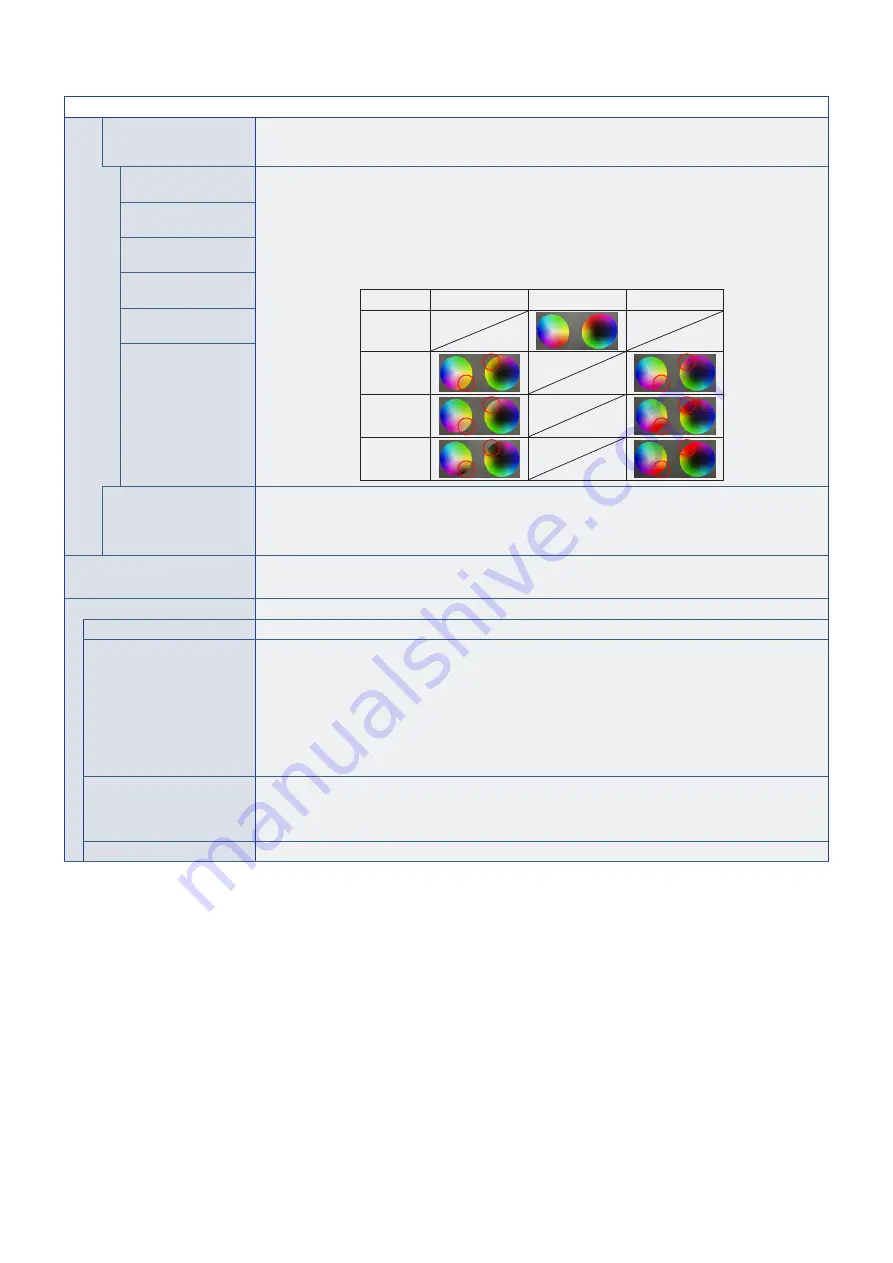
6 AXIS COLOR TRIM

With these controls, the standard color circle is divided into 6 separate ranges/areas: Reds, Yellows, 

Greens, Cyans, Blues, and Magentas. Each range can be individually adjusted in Hue, Saturation, and 

Offset (Brightness) for specific matching purposes. Neutral colors (grays) will not be impacted.

RED (HUE/SAT./

OFFSET)

HUE:  

 Changes the actual color within its range on the color wheel without changing the 

saturation and offset. For example, the Red color range shifts reds towards Yellow or 

Magenta, the Yellow color range shifts yellows towards Red or Green, and so on.

SAT. (Saturation):  Changes the intensity of the color range without changing the hue and offset.
OFFSET: 

Changes the brightness of the color range without changing the hue and saturation.

e.g.: This is the color changes when Red color set to minimum  

value and maximum value at HUE/SAT./OFFSET. 

Minimum value

0

Maximum value

Default

HUE

SAT.

OFFSET

YELLOW (HUE/SAT./

OFFSET)
GREEN (HUE/SAT./

OFFSET)
CYAN (HUE/SAT./

OFFSET)
BLUE (HUE/SAT./

OFFSET)
MAGENTA (HUE/SAT./

OFFSET)

UNIFORMITY

This function improves the color reproduction and evens out the non-uniformity in luminance of the 

monitor.
NOTE: 

A higher number produces a better effect, but may also affect power consumption and lifetime of 

the monitor.

BACKLIGHT DIMMING 

When [SPECTRAVIEW ENGINE] 

is set to [ON]

Automatically adjusts each of the clusters of the backlight of the LCD independently, according to the input 

signal.

SPECTRAVIEW ENGINE

SPECTRAVIEW ENGINE

Select [ON] to activate [SPECTRAVIEW ENGINE] (see 

page 45

).

NUMBER OF PICT. MODES

Limits the number of selectable Picture Modes.
Limiting the number of selectable Picture Modes can be used for the following purposes:
•  Locking. 

By setting to [1], it will prevent other Picture Modes from being accessed and adjusted.

•  Skip. 

If there are unused Picture Modes that aren’t needed, they can be skipped when using the Picture 

Mode button on the remote control to toggle modes. For example, if [3] is set for [NUMBER OF PICT. 

MODES], the available picture modes are [1, 2, 3] and the other modes will be skipped.

METAMERISM

Improves the white point color matching when the display is used side-by-side with a standard gamut 

display monitor. This feature compensates for the way the human eye perceives colors slightly differently 

compared to the scientific instrument used to adjust the monitor during calibration. This function should be 

disabled in color critical applications.

CALIBRATION

Starts the “Stand-Alone Calibration” when using a USB color sensor. See 

page 49

.

Summary of Contents for MultiSync M981

Page 1: ...User s Manual Large Format Display MultiSync M981 MODEL M981 Please find your model name on the label on the rear side of the monitor...

Page 2: ...Panel 22 Terminal Panel 23 Wireless Remote Control 25 Chapter 3 Connections Wiring Diagram 28 Connecting to a Personal Computer 29 Connecting to a Media Device with HDMI 29 HDMI CEC Command 31 HDMI CE...

Page 3: ...Monitor Setup Connecting Multiple Monitors 57 Video Out Connection 60 Setting the Remote Control ID Function 61 Chapter 7 External Control Controlling the Monitor via RS 232C 63 Controlling the Monito...

Page 4: ...B External Resources Appendix C OSD Controls List INPUT 86 PICTURE 89 AUDIO 96 SCHEDULE 97 SLOT 98 NETWORK 100 PROTECT 101 SYSTEM 103 Appendix D Manufacturer s Recycling and Energy Information Dispos...

Page 5: ...S Government Printing Office Washington D C 20402 Stock No 004 000 00345 4 SUPPLIER S DECLARATION OF CONFORMITY This device complies with Part 15 of the FCC Rules Operation is subject to the followin...

Page 6: ...prohibited action This symbol indicates a mandatory action WARNING UNPLUG THE POWER CORD Unplug the power cord if the product malfunctions Should the product emit smoke or strange odors or sounds or...

Page 7: ...es with the safety standards in the country of purchase MUST BE EARTHED This equipment is designed to be used in the condition of the power cord connected to the earth If the power cord is not connect...

Page 8: ...of injury but may not guarantee the effectiveness against all earthquakes The product may tip causing personal injury When using the product with the optional table top stand fasten the product to a...

Page 9: ...ed the same considerations as above should be applied PROHIBITED Do not place this product on a sloping or unstable cart stand or table Doing so could lead to falling or tipping and cause personal inj...

Page 10: ...k that all cables connecting the product to other devices are disconnected PROHIBITED Do not use the power cord with a power tap Adding an extension cord may lead to fire as a result of overheating PR...

Page 11: ...en or mechanically crushing cutting or modifying a battery can result in an explosion Do not short circuit the batteries Do not charge the batteries The batteries provided are not rechargeable Contact...

Page 12: ...rd input signals Use the preset color settings Use non interlaced signals Do not view the primary color blue on a dark background It is difficult to see and may cause eye fatigue due to insufficient c...

Page 13: ...eration status management control Compatibility with NaViSet Administrator 2 enables network operation of multiple NEC monitors and projectors as well as network based asset management Simple tile mat...

Page 14: ...g for Trained Installers on page 15 Please read Important Information carefully before installation NOTE For box contents please refer to the Setup Manual provided in the box Product warranty does not...

Page 15: ...control is powered by two 1 5 V AAA batteries To install or replace batteries 1 2 3 NOTE If you do not intend to use the remote control for a long period of time remove the batteries Use manganese or...

Page 16: ...cable Use of other cables and adapters may cause interference with radio and television reception 6 Turn on the power for the monitor and the external equipment Switch on the monitor power first 7 Ope...

Page 17: ...e main unit or the STANDBY button on the remote control to put the unit in standby mode Use POWER SAVE SETTINGS in the PROTECT OSD menu When there is no input signal the monitor will automatically swi...

Page 18: ...eck the mounting location for signs of damage or weakness that may occur over time Changing the Logo Ornament Position When using the monitor in the portrait position the logo ornament position can be...

Page 19: ...heat can properly dissipate away from the monitor and from the mounting equipment Please note the following when mounting on a wall or ceiling We recommend mounting interfaces that comply with UL1678...

Page 20: ...to the LCD panel or excessive force to any part of the monitor by pushing or leaning on it This may cause the monitor to become distorted or damaged Handles for safety wire Attach the safety wire to t...

Page 21: ...installed in the wrong orientation heat may be trapped inside the main unit and the lifetime of the monitor may be shortened It cannot be installed upside down NOTE When you rotate the monitor in the...

Page 22: ...he unit and the mounting equipment especially when you use monitors in a multiple screen configuration This monitor has internal temperature sensors If the monitor overheats a Caution warning appears...

Page 23: ...tion This monitor and bracket must be installed on a wall which can endure at least 4 times or more the weight of the monitor Install by the most suitable method for the material and the structure M10...

Page 24: ...g equipment Use only those devices recommended by the manufacturer NOTE Use the ST 801 ONLY use screws which are included with the optional table top stand Install the stand so the long end of the fee...

Page 25: ...English 21 Chapter 2 Parts Names and Functions This Chapter Includes Control Panel on page 22 Terminal Panel on page 23 Wireless Remote Control on page 25...

Page 26: ...playPort2 HDMI1 HDMI2 OPTION 1 COMPUTE MODULE 2 Input names are shown as their factory preset name 1 This function depends on which Option Board is installed in the monitor 2 This input is available w...

Page 27: ...le Monitors Connection see page 65 6 REMOTE Use an optional sensor unit by connecting it to your monitor NOTE Do not use this connector unless specified When the optional sensor unit is connected the...

Page 28: ...e with Kensington security cables equipment NOTE For products visit Kensington s website Label Raspberry Pi Compute Module Slot Slot for installing a Raspberry Pi Compute Module Interface Board and Ra...

Page 29: ...been locked in the LOCK SETTINGS in the PROTECT menu Press and hold the DISPLAY button for more than five seconds to unlock the remote See page 54 7 MENU Button Opens and closes the OSD menu See page...

Page 30: ...s released if any following functions is changed ASPECT MULTI PICTURE TILE MATRIX MOTION in SCREEN SAVER POINT ZOOM IMAGE FLIP QUICK INPUT CHANGE OVERSCAN DUAL DAISY CHAIN MODE if you change the AUDIO...

Page 31: ...ning on the monitor s main power or other external equipment s power as this may result in loss of image Do not use an attenuating built in resistor audio cable Using an audio cable with a built in re...

Page 32: ...e power supply Ex Multi Presenter stick HDMI video player or Computer HDMI Blu ray or DVD Player HDMI AV Amplifier Computer DisplayPort USB devices such as an USB camera or USB storage device 1 Comput...

Page 33: ...he lock To output DisplayPort audio set DisplayPort1 or DisplayPort2 at AUDIO INPUT in the OSD or choose DisplayPort1 or DisplayPort2 using the remote control AUDIO INPUT button If the monitor s main...

Page 34: ...e manufacturer may only provide compatibility with its own monitors or TVs See HDMI CEC Command on page 31 When supported the monitor s remote control can be used to control the HDMI media device NOTE...

Page 35: ...anguage which is selected for the monitor For the Change Language function it is necessary that the connected HDMI CEC compatible device be able to cope with multi language POWER CONTROL LINK System S...

Page 36: ...English 32 HDMI CEC Remote Control button functions HDMI CEC MODE1 HDMI CEC MODE2...

Page 37: ...20CE Compute Module Interface Board and Raspberry Pi Compute Module are available separately Please contact an authorized dealer for more information Installation must be performed by a qualified tech...

Page 38: ...a or presenter sticks The actual amount of power consumption depends on the connected device Make sure to use a USB cable that supports 2A Enable USB POWER in the USB settings of the SYSTEM menu in th...

Page 39: ...on page 36 Operating Range for the Remote Control on page 37 Using Power Management on page 37 Showing the Information OSD on page 38 Switching Between Picture Modes on page 38 Setting the Aspect Rati...

Page 40: ...ABLE Glowing amber No AV signal input has been detected by the monitor during the period of time you set with network signal input Blinking amber No AV signal input has been detected by the monitor du...

Page 41: ...ption of the monitor when it is not in use When connected to a computer power consumption by the monitor reduces automatically if the keyboard or mouse are not used during the time set in the computer...

Page 42: ...ation 3 HDR Information 4 Communication Info Shows when COMMUNICATION INFO is ON Green Connected LAN Red Not connected LAN Switching Between Picture Modes Press the PICTURE MODE button on the wireless...

Page 43: ...Compute Module Interface Board and Raspberry Pi Compute Module are installed Aspect ratio of image Unchanged view 3 Recommended selection for picture aspect 3 Description 4 3 NORMAL Reproduces the asp...

Page 44: ...N SAVER TILE MATRIX MULTI PICTURE IMAGE FLIP QUICK INPUT CHANGE MODE1 or MODE2 in CEC DUAL DAISY CHAIN MODE ROTATE or if input is set to DisplayPort1 and the DisplayPort VERSION is set to 1 4 The STIL...

Page 45: ...INE ADVANCED NATIVE RETAIL CONFERENCING HIGHBRIGHT TRANSPORTATION CUSTOM Input source Main Menu Icons Main Menu Item Sub Menu Key Guide Adjustment Settings Remote Control Press or to navigate to a sub...

Page 46: ...nd select settings related to the audio SCHEDULE Create auto power on off schedules set the daylight savings time and off timer SLOT Select settings related to an Option Board if installed NETWORK Set...

Page 47: ...r 5 Advanced Operation This Chapter Includes Creating a Power Schedule on page 44 Advanced Color Adjustment on page 45 Using Other Picture Modes on page 51 Setting Security and Locking the Monitor Con...

Page 48: ...HEDULE INFORMATION window If multiple schedules are set to start at the same time the conflicting schedule with the highest number is given priority Schedules will not run when the OFF TIMER is set to...

Page 49: ...r management features and the user color controls allow a unique level of precision to be achieved The white point is adjusted using a CIE x y control and the grayscale response of the display is calc...

Page 50: ...ndows operating systems and many smart phone and other digital cameras Recommended setting for general color management AdobeRGB Wider color gamut setting used in high end graphics applications such a...

Page 51: ...PQ luminance range A larger value will improve white saturation but the picture become darker When Auto is selected Luminance is used as the peak luminance setting DICOM DICOM GSDF Grayscale Standard...

Page 52: ...ly takes screen measurements directly from the color sensor See Appendix A for purchase and availability information Or A near range colorimeter with a measurement readout display in CIE Y x y format...

Page 53: ...a the OSD using the remote control Y is in units of cd m2 Depending on the monitor usage and other factors performing a Self Calibration at least once per year is recommended Reset calibration This de...

Page 54: ...that will be used as the Target or source of the copy operation A This function will measure the luminance and white point of the target monitor A and set these values to the current Picture Mode of...

Page 55: ...HT TRANSPORTATION CUSTOM 1 This function depends on which Option Board is installed in the monitor 2 This input is available when the optional Raspberry Pi Compute Module Interface Board and Raspberry...

Page 56: ...ions for Security and Lock Settings are in the PROTECT menu in both the OSD menu and web controls PASSWORD o o o o SECURE MODE START UP LOCK CONTROL LOCK CHANGE PASSWORD CURRENT PASSWORD o o o o NEW P...

Page 57: ...nable password security PASSWORD o o o o SECURE MODE START UP LOCK CONTROL LOCK PROTECT POWER SAVE SETTINGS THERMAL MANAGEMENT SCREEN SAVER POWER ON DELAY SECURITY SETTINGS LOCK SETTINGS ALERT MAIL 1...

Page 58: ...nder MODE choose the lock mode you want to enable UNLOCK all buttons are unlocked ALL LOCK all buttons are locked CUSTOM LOCK all remote buttons are locked except for the following buttons that can be...

Page 59: ...ume adjustment MIN VOL and MAX VOL the v w keys are unlocked and the volume can only be adjusted within the MIN and MAX set The VOLUME must be set to UNLOCK for this setting to operate NOTE Volume MIN...

Page 60: ...English 56 Chapter 6 Multi Monitor Setup This Chapter Includes Connecting Multiple Monitors on page 57 Video Out Connection on page 60 Setting the Remote Control ID Function on page 61...

Page 61: ...VERSION HDMI MODE VIDEO OUT SETTINGS and Input signal NOTE MONITOR ID in AUTO ID IP SETTING will be automatically executed This function is released if MOTION in SCREEN SAVER is activated If input is...

Page 62: ...ting 3 at POSITION After individually setting the 1x2 image Portrait configuration will be shown as below SYSTEM EXTERNAL CONTROL sets the monitor ID and group IP for the current monitor When the moni...

Page 63: ...sing the same monitor model for all monitors in the connected daisy chain MONITORS POSITION is different from ID Please refer to the figure 1 H MONITORS 3 V MONITORS 3 POSITION 4 5 6 ID 1 1 ID 6 4 ID...

Page 64: ...stop This monitor s signal output function supports contents protected by HDCP HDCP content can be distributed across multiple connected monitors as described below HDCP1 3 1 4 Up to 8 monitors inclu...

Page 65: ...ntrol to Control all Monitors in Range 1 On the remote control press and hold down the REMOTE ID SET button while using the keypad to input the REMOTE CONTROL ID number 0 2 All monitors within range o...

Page 66: ...ds on page 73 Proof of Play on page 74 Connecting an external device There are two options to connect an external device to control the monitor RS 232C terminal Connecting an external device to the RS...

Page 67: ...power If you turn on the computer and monitor in reverse order the com port may not work To control the monitor via commands sent from a computer connected with an RS 232C cable please use the contro...

Page 68: ...g the Monitor via LAN Connecting to a Network Using a LAN cable allows you to specify the Network Settings and the Alert Mail Settings by using an HTTP server function To use a LAN connection you are...

Page 69: ...ion on the network A loop connection occurs when both LAN 1 and LAN 2 on a single monitor is connected to the same network NOTE In a LAN daisy chain only the first monitor should be connected to the n...

Page 70: ...moment and repeat If you still can t get a response turn the monitor off and then back on Preparation Before Use Operation with a browser that uses a proxy server may not be possible depending on the...

Page 71: ...eb controls Select one of the links on the left side of the monitor web controls to configure the settings available in the monitor s OSD Please see page 85 for the full list of OSD menu controls INPU...

Page 72: ...network when MANUAL is selected for IP SETTING DEFAULT GATEWAY Set your default gateway for the monitor connected to the network when MANUAL is selected for IP SETTING NOTE Set as 0 0 0 0 to delete t...

Page 73: ...authentication of the email User Name This sets the user name for logging into the authentication server when authentication is required for the email transmission Up to 60 alphanumeric characters ca...

Page 74: ...Error code Temperature Temperature abnormal 0xA0 0xA1 0xA2 Fan Cooling fan abnormal 0x80 0x81 Power Power abnormal 0x70 0x71 0x72 0x78 Inverter Backlight Inverter or backlight abnormal 0x90 0x91 No Si...

Page 75: ...ON SERVER IP ID HINT The CRESTRON settings are required only for use with CRESTRON ROOMVIEW For further information visit http www crestron com Name Settings Click on NAME on the left hand column belo...

Page 76: ...long Do not forget your password If you forget your password consult your supplier HTTP PASSWORD Set a password for the HTTP server The password must be max 10 characters long HTTP PASSWORD ENABLE An...

Page 77: ...the External_Control pdf See page 83 but also supports common ASCII control command which is used for controlling the NEC monitor or projector from a connected computer For further information please...

Page 78: ...econd g EXPANSION DATA 00h Normal Proof of Play event 01h Proof of Play event is last power on time 20h Contents Copy from USB 21h Contents Copy form network folder 30h Contents Copy Success 31h Conte...

Page 79: ...English 75 Chapter 8 Troubleshooting This Chapter Includes Screen Image and Video Signal Issues on page 76 Hardware Issues on page 77...

Page 80: ...o the decision intention of the HDCP community Digital Content Protection LLC Image persistence Please be aware that LCD Technology may experience a phenomenon known as image persistence Image persist...

Page 81: ...hites can occur when the VIDEO RANGE is set to FULL while the source video signal s color levels are RGB Limited RGB 16 235 which effectively appears to prevent the monitor from obtaining its full bri...

Page 82: ...tion to OFF The monitor may go into standby mode when a connected HDMI CEC supported device goes into standby Please check POWER in the SCHEDULE INFORMATION Power Indicator Patterns LED on the monitor...

Page 83: ...English 79 Chapter 9 Specifications This Chapter Includes Compatible signal list on page 80 M981 on page 81...

Page 84: ...image 4096 x 2160 65 7 kHz 30 Hz No No Yes Compressed image 4096 x 2160 67 5 kHz 30 Hz No Yes No Compressed image 4096 x 2160 112 5 kHz 50 Hz No Yes No Compressed image 4096 x 2160 133 3 kHz 60 Hz No...

Page 85: ...V 50 60 Hz Power Consumption Normal Operation 5 Energy Saving Mode 5 LED glowing amber Energy Saving Mode 5 LED blinking amber Approx 340 W 2 W or less 0 5 W or less Operational Environment Temperatu...

Page 86: ...ce HDMI Trade Dress and the HDMI Logos are trademarks or registered trademarks of HDMI Licensing Administrator Inc PJLink trademark and logo are trademarks applied for registration or are already regi...

Page 87: ...ions protocol into a Python library for rapid development https github com SharpNECDisplaySolutions necpdsdk Projector Monitor Common ASCII Control Command Reference Manual PDF document This document...

Page 88: ...is available for purchase and may require the use of a supported external color sensor Please contact an authorized dealer or see our website in your region for purchase information and availability...

Page 89: ...Controls List This Chapter Includes INPUT on page 86 PICTURE on page 89 AUDIO on page 96 SCHEDULE on page 97 SLOT on page 98 NETWORK on page 100 PROTECT on page 101 SYSTEM on page 103 Default values c...

Page 90: ...s not search for video signal on the other input connections If video signal is lost on the current input or if the monitor is manually switched to an input that does not have video signal the screen...

Page 91: ...ied Deactivates MULTI PICTURE MOTION in SCREEN SAVER STILL POINT ZOOM IMAGE FLIP QUICK INPUT CHANGE DUAL DAISY CHAIN MODE AUDIO INPUT ROTATE TILE COMP TILE CUT and DP to HDMI CONVERT H MONITORS and V...

Page 92: ...or Only available for HDMI inputs CEC When MODE1 or MODE2 is selected the following functions are automatically activated Also when the compatible device is started from standby mode this unit also wo...

Page 93: ...e video signal input from the DisplayPort terminal to HDMI and outputs to HDMI terminal NOTE If input is set to DisplayPort1 and the DisplayPort VERSION is set to 1 4 this function is deactivated RESE...

Page 94: ...s suitable for various environments where this device may be used or customize settings to viewer preference PICTURE MODE Five customizable Picture Mode memories 1 2 3 4 or 5 See page 45 EMULATION 3D...

Page 95: ...or NOTE A higher number produces a better effect but may also affect power consumption and lifetime of the monitor BACKLIGHT DIMMING When SPECTRAVIEW ENGINE is set to ON Automatically adjusts each of...

Page 96: ...1 by 1 Pixel format If the input resolution is higher than the recommended resolution the image will be scaled down to fit the screen ZOOM Expands reduces the image NOTE The areas of the expanded ima...

Page 97: ...IGHT SENSING is set BACKLIGHT and MODE1 in AUTO BRIGHTNESS functions are disabled Do not select this function when AUTO BRIGHTNESS function is set to MODE1 Do not cover the optional sensor unit when A...

Page 98: ...ontally V MONITORS Number of monitors arranged vertically POSITION Select the section of the tiled image to view on the current monitor TILE COMP Adjusts the image to compensate for the gap between mo...

Page 99: ...is enabled When either picture is selected the sound of that picture is output NOTE This function deactivates AUDIO INPUT ACTIVE PICTURE When MULTI PICTURE MODE is OFF PICTURE1 is the active picture...

Page 100: ...iewer preference NATIVE Standard setting RETAIL Surround sound for clarity of audio in retail stores CONFERENCING Optimized settings for clarity of audio in conference rooms HIGHBRIGHT Lowest volume l...

Page 101: ...s back to factory settings except for AUDIO MODE This function is only available when Raspberry Pi Compute Module Interface Board and Raspberry Pi Compute Module are installed See page 83 1 This funct...

Page 102: ...ed then a device is not installed Power Status 3 Shows the operating status of the installed Option Board Module 3 Shows information about the installed Option Board POWER SETTING AUTO POWER UP The in...

Page 103: ...S of the device This message cannot be changed This message displays when POWER SUPPLY is set to OFF ADVANCED SETTING SHUTDOWN SIGNAL Enables or disables the use of GPIO 23 to signal that power to the...

Page 104: ...NOTE Enter 0 0 0 0 to delete the setting DNS SECONDARY Enter the secondary DNS server settings of the network connected to the monitor NOTE Enter 0 0 0 0 to delete the setting MAC ADDRESS Shows the mo...

Page 105: ...SSAGE Shows a message as the monitor is entering low power mode QUICK START When ENABLE is selected the monitor will quickly return to the ON state when a signal is detected Enabling this option incre...

Page 106: ...tween when the POWER ON button is pressed and when the power actually turns on is 95 seconds This allows the 19 monitors in the multi monitor installation to turn on with 5 second intervals between ea...

Page 107: ...t Savings is not in effect Then enable the DAYLIGHT SAVING function to have the clock automatically adjust to the current time If the INTERNET TIME SERVER is set to ON this function is disabled CURREN...

Page 108: ...mbers starting from this number and counting up by 1 to each monitor in the LAN chain When running AUTO ID Monitor numbers can be between 1 99 However the master monitor must have a starting number lo...

Page 109: ...d of inactivity The preset choices are 10 240 seconds OSD POSITION Determines the location where the OSD appears on the screen OSD SIZE Change the size of the OSD on the screen INFORMATION OSD Selects...

Page 110: ...SET to initiate import or export of the OSD menu settings This field is enabled when CLONE SETTING is set to USB WRITE Pressing SET will initiate exporting the OSD menu settings to an attached USB st...

Page 111: ...USB B when EXTERNAL PC is set USB POWER Supplies power to the USB Service 2A port Select ON to supply power during standby NOTE Power consumption by devices connected to this port depends on the USB...

Page 112: ...ge 109 We are strongly committed to environmental protection and sees recycling as one of the company s top priorities in trying to minimize the burden placed on the environment We are engaged in deve...

Page 113: ...information visit https www sharpnecdisplays us in USA https www sharpnecdisplays eu p hq en home xhtml in Europe https www sharp nec displays com global index html Global WEEE Mark European Directiv...

Reviews: