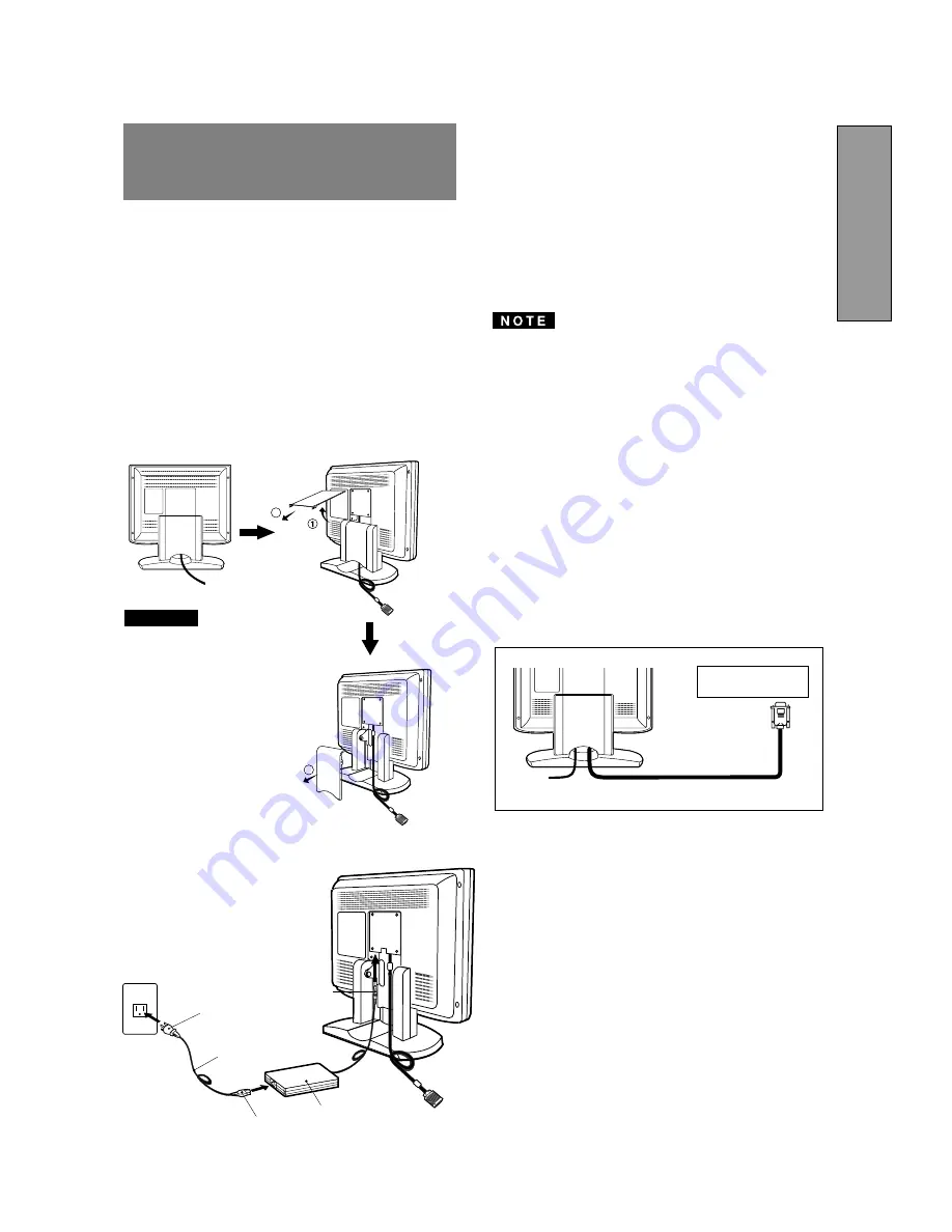
background image

- 1-7 -

ENGLISH

 Signal Cable

High Resolution

Graphic Video Card

Figure 5

3.2

Signal Cable Connection

The attached video signal cable provides a D-SUB-15P
connector for the VGA compatible analog RGB outputs on
your computer.  Apple Macintosh Computers can also be
interfaced using the optional Macintosh adapter.

The Sync-On-Green signal involving equalizing pulse
is not applicable to the monitor.

Don't input the Sync-On-Green signal and separate
sync signal to the monitor at the same time.  It may
make the screen abnormal.

3.2.1 Connecting to Any IBM VGA Compatible Sys-

tem

Figure 5 shows the signal cable connection to the Video
Graphics Array (VGA) port in an IBM Personal System/2

®

or any VGA compatible system.

1. Power off, the monitor and the computer.
2. Connect the one end of the signal cable to the 15-pin

connector on the VGA controller card.

3. Power on the monitor, then the computer.
4. After using the system, power off the monitor, then the

computer.

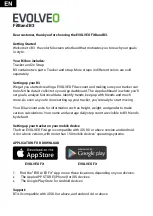
On the back of the monitor are three plug-in connec-
tions:  one for the DC power connection and others for
the video signal connection.

3.1

AC Power Connection

Remove the cable covers.  The DC jack from the AC
Adapter is connected into the DC power connector on the
back of the monitor.  One end of the power cord is
connected into the AC Adapter, and another end of the
power cord is plugged into a AC outlet. The monitor’s auto-
sensing AC Adapter can automatically follow the AC input.

The socket-outlet shall be
installed near the equipment
and shall be easily acces-
sible.  During servicing, dis-
connect the plug from the
socket-outlet.
Do not use this AC Adapter
to other equipments, as this
can cause a fire.
When operating the LCD
monitor with its AC220-240V
worldwide power supply,use
a power supply cord that
matches the power supply
voltage of the AC power
outlet being used.The power
supply cord you use must
have been approved by and
comply with the safety stan-
dards of your country.

Plug

CAUTION

Power Cord

Receptacle

AC Adapter

DC Jack

<How to remove the covers>

3

2

3

3

INSTALLATION AND
CONNECTION

Summary of Contents for MULTISYNC LCD1800TM

Page 1: ...IAL No The serial number is located on the rear cover of the monitor AUTO SCANNING WITH DIGITAL CONTROL LCD COLOR DISPLAY MONITOR MultiSync LCD1800 SELECT ADJUST OSD OFF SIGNAL A B Supplying Windows 9...

Page 2: ...r Connect the equipment into an outlet on a circuit different from that to which the receiver is con nected Consult the dealer or an experienced radio TV tech nician for help NO USER SERVICEABLE PARTS...

Page 3: ...ability Below you will find a brief summary of the environmental requirements met by this product The complete environmental criteria document may be ordered from TCO Development SE 114 94 Stockholm S...

Page 4: ...TSUBISHI ELECTRIC VISUAL SYSTEMS CORPORATION makes no representa tions to the contrary Life support devices are those devices which are used to measure diagnose or evaluate the tissue systems or funct...

Page 5: ...anager System Provides innovative power saving methods that allow the monitor to shift to a lower power consumption level when on but not in use saving two thirds of your monitor energy costs reducing...

Page 6: ...of 1024 dots by 768 lines or lower is inputted to the monitor With some resolution even if it meets the condition above the screen is not expanded fully to the screen area With some signal type inputt...

Page 7: ...e power cord can cause a fire or electrical shock When transporting the monitor handle it with care Avoid giving any shock or scratch to the screen as the screen is fragile 1 12 Cleaning Your Monitor...

Page 8: ...1 15 Quick Operation Chart To summarize the steps in connecting your computer and adapter with MultiSync LCD1800 color LCD monitor and setting the necessary controls and switches refer to the chart be...

Page 9: ...Under the OSM off condition Push to select the signal input connector which is connected to the computer which you want to use Under the OSM on condition Push to turn off OSM FUNCTION SELECT BUTTONS...

Page 10: ...onitor then the computer On the back of the monitor are three plug in connec tions one for the DC power connection and others for the video signal connection 3 1 AC Power Connection Remove the cable c...

Page 11: ...omputer Apple Macintosh Computer Signal Cable 3 2 2 Connecting to An Apple Macintosh Computer Figure 6 shows the signal cable and Macintosh Adapter to the video port in an Apple Macintosh 1 Power off...

Page 12: ...the monitor is used with an interlace signal of resolution 1280 dots by 1024 lines one line in the top or bottom of the screen is lost This condition can not be corrected by any adjustment Conduct the...

Page 13: ...Auto Bright Function To on the Auto Bright Function To narrow the width of the image on the screen to the left To change the snow noise of the image To expand the width of the image on the screen to t...

Page 14: ...te OSM again 5 2 CONTROL LOCK Mode Operation ADJUST ADJUST SELECT ADJUST Press and buttons together to restore to the factory preset level Press ALL RESET to restore to the factory preset level Group...

Page 15: ...is active Input signal frequency range is out of specification Display Resolution is out of range Signal cable disconnected Computer power switch Power management function is active Adjust RESOLUTION...

Page 16: ...Typ SIGNAL INPUT CONNECTORS D SUB 15P One is with the detachable signal cable and another is behind the cable cover OPERATING Temperature 5 35 C ENVIRONMENT Humidity 10 90 RH without condensation POW...

Page 17: ...NEC MITSUBISHI for service MUST have prior approval which may be obtained by calling 1 800 632 4662 The Product shall not have been previously altered re paired or serviced by anyone other than a serv...

Reviews: