background image

- 1-10 -


Press         and          buttons together, to restore to the factory preset level.

Press "ALL RESET" to restore to the factory preset level.
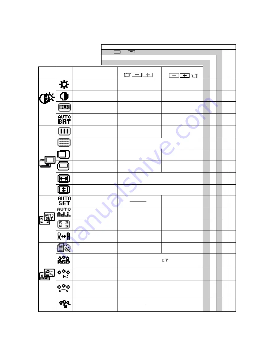
To be deep of black
color.

To be light of black
color.

To move the image to
the left.

To move the image
to the right.

To move the image
down.

To move the image
up.

To display by TEXT
mode.

To restore to the color tem-
perature and color control to
the factory preset.

To adjust the height of the image on the screen.

To adjust the width of the image on the screen.

Group

Icon

Press the Minus Button:

Press the Plus Button:

Item
Icon

Item

T o   d e c r e a s e   t h e
brightness.

T o   i n c r e a s e   t h e
brightness.

To decrease the con-
trast.

To increase the con-
trast.

To display by  GRAPHIC
mode.

Set data by each timing.

Set data does not change by the changing of the signal timing.

To conduct Auto Setup.

To off the Auto Bright
Function.

To on the Auto Bright
Function.

To narrow the width of

the image on the screen

to the left.

To change the snow noise of the image.

To expand the width

of the image on the

screen to the right.

5.1

Adjustment Items

To decrease the color
temperature.

To increase the color
temperature.

To off the Auto Adjust-
ment Function.

To on the Auto Adjust-
ment Function.

Factory Presets

User Presets

Select the desired Color from sRGB, VIDEO
NATIVE and CUSTOM.  (        P1-4)
(sRGB, VIDEO, NATIVE: Unadjustable.)

To decrease the
distinction.

To increase the
distinction.

The color of screen is
adjusted to the "-"
symbol's color at Level-
bar's left side.

The color of screen is
adjusted to the "+"
symbol's color at Level-
bar's right side.

To set the normal screen
area.

To set the expanded
screen area.

BRIGHTNESS

○ ○ ○

CONTRAST

○ ○ ○

BLACK LEVEL

○ ○ ○

AUTO BRIGHTNESS

○ ○

CLOCK

CLOCK PHASE

HORIZONTAL POSITION

VERTICAL POSITION

H RESOLUTION

V RESOLUTION

AUTO SETUP

AUTO ADJUST

EXPAND

 SHARPNESS

○ ○

DISPLAY MODE

○ ○

COLOR

○ ○

COLOR TEMPERATURE

○ ○ ○

COLOR CONTROL

○ ○ ○

COLOR RESET

Summary of Contents for MULTISYNC LCD1800TM

Page 1: ...IAL No The serial number is located on the rear cover of the monitor AUTO SCANNING WITH DIGITAL CONTROL LCD COLOR DISPLAY MONITOR MultiSync LCD1800 SELECT ADJUST OSD OFF SIGNAL A B Supplying Windows 9...

Page 2: ...r Connect the equipment into an outlet on a circuit different from that to which the receiver is con nected Consult the dealer or an experienced radio TV tech nician for help NO USER SERVICEABLE PARTS...

Page 3: ...ability Below you will find a brief summary of the environmental requirements met by this product The complete environmental criteria document may be ordered from TCO Development SE 114 94 Stockholm S...

Page 4: ...TSUBISHI ELECTRIC VISUAL SYSTEMS CORPORATION makes no representa tions to the contrary Life support devices are those devices which are used to measure diagnose or evaluate the tissue systems or funct...

Page 5: ...anager System Provides innovative power saving methods that allow the monitor to shift to a lower power consumption level when on but not in use saving two thirds of your monitor energy costs reducing...

Page 6: ...of 1024 dots by 768 lines or lower is inputted to the monitor With some resolution even if it meets the condition above the screen is not expanded fully to the screen area With some signal type inputt...

Page 7: ...e power cord can cause a fire or electrical shock When transporting the monitor handle it with care Avoid giving any shock or scratch to the screen as the screen is fragile 1 12 Cleaning Your Monitor...

Page 8: ...1 15 Quick Operation Chart To summarize the steps in connecting your computer and adapter with MultiSync LCD1800 color LCD monitor and setting the necessary controls and switches refer to the chart be...

Page 9: ...Under the OSM off condition Push to select the signal input connector which is connected to the computer which you want to use Under the OSM on condition Push to turn off OSM FUNCTION SELECT BUTTONS...

Page 10: ...onitor then the computer On the back of the monitor are three plug in connec tions one for the DC power connection and others for the video signal connection 3 1 AC Power Connection Remove the cable c...

Page 11: ...omputer Apple Macintosh Computer Signal Cable 3 2 2 Connecting to An Apple Macintosh Computer Figure 6 shows the signal cable and Macintosh Adapter to the video port in an Apple Macintosh 1 Power off...

Page 12: ...the monitor is used with an interlace signal of resolution 1280 dots by 1024 lines one line in the top or bottom of the screen is lost This condition can not be corrected by any adjustment Conduct the...

Page 13: ...Auto Bright Function To on the Auto Bright Function To narrow the width of the image on the screen to the left To change the snow noise of the image To expand the width of the image on the screen to t...

Page 14: ...te OSM again 5 2 CONTROL LOCK Mode Operation ADJUST ADJUST SELECT ADJUST Press and buttons together to restore to the factory preset level Press ALL RESET to restore to the factory preset level Group...

Page 15: ...is active Input signal frequency range is out of specification Display Resolution is out of range Signal cable disconnected Computer power switch Power management function is active Adjust RESOLUTION...

Page 16: ...Typ SIGNAL INPUT CONNECTORS D SUB 15P One is with the detachable signal cable and another is behind the cable cover OPERATING Temperature 5 35 C ENVIRONMENT Humidity 10 90 RH without condensation POW...

Page 17: ...NEC MITSUBISHI for service MUST have prior approval which may be obtained by calling 1 800 632 4662 The Product shall not have been previously altered re paired or serviced by anyone other than a serv...

Reviews: