


Setting Up the System 2-9
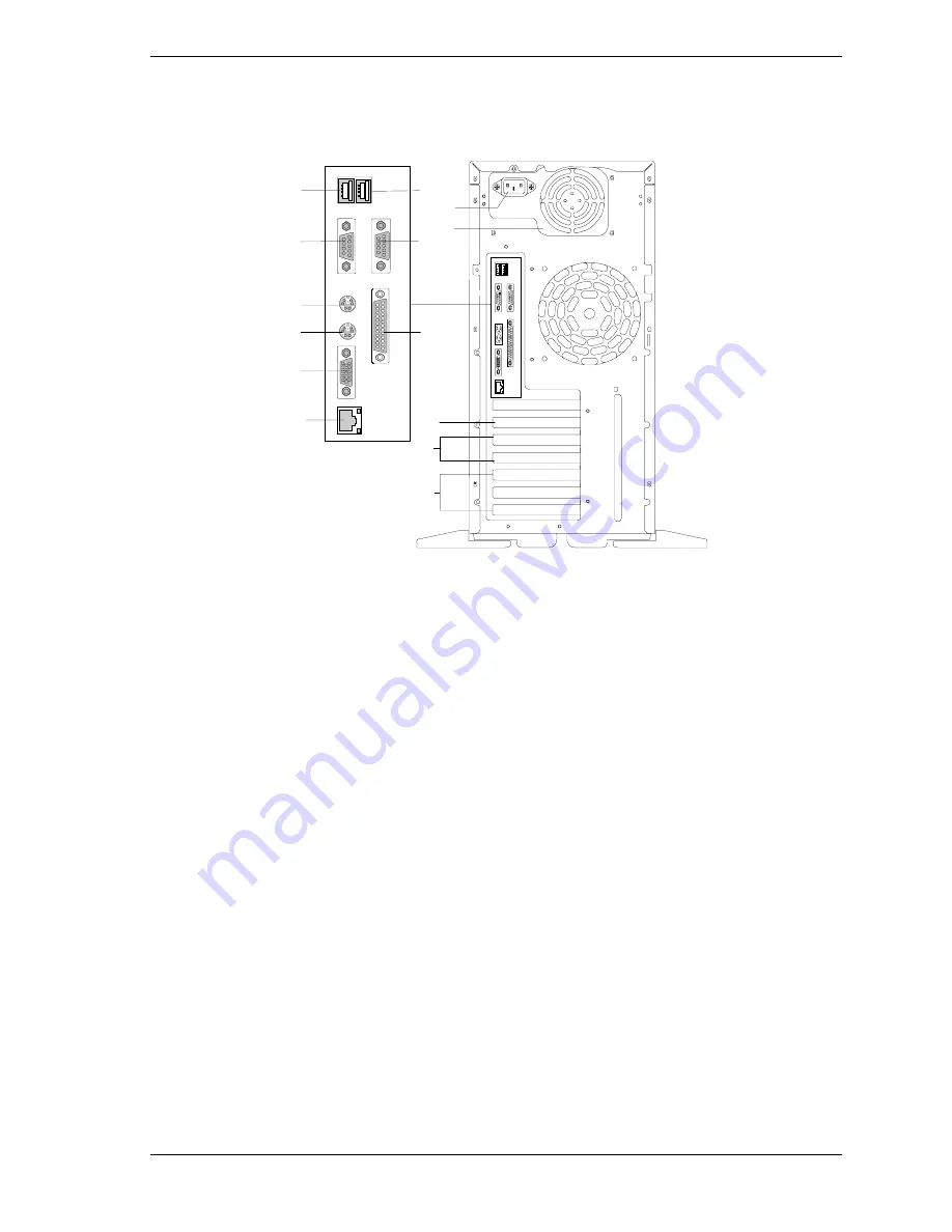
Rear View
Figure 2-6 shows the location of the following rear system features and controls.
I
J
B
A
C
D
E
F
G
H
K
L
M
N
A
USB2 connector
Second USB connector (Black)
B
USB1 connector
First USB connector (Black)
C
Serial port 2
COM2 serial port 9-pin connector (Turquoise)
D
Serial port 1
COM1 serial port 9-pin connector (Turquoise)
E
Mouse connector
PS/2-compatible 6-pin mini-DIN connector (Green)
F
Printer port
Parallel port 25-pin connector (Burgundy)
G
Keyboard
connector
PS/2-compatible 6-pin mini-DIN connector (Purple)
H
SVGA monitor
connector
SVGA monitor 15-pin connector (Blue)
I
LAN connector
RJ-45 Ethernet connector
J
AC input power
connector
Supplies ac power to the power supply
K
Power supply
300watt, auto-sensing power supply
L
32-bit, 33MHz,
PCI slot
Single 32-bit, 33MHz PCI add-in board slot location
M
64-bit, 66MHz,
PCI slots
Two 64-bit, 66MHz PCI add-in board slot locations
N
32-bit, 33MHz,
PCI slots
Three 32-bit, 33MHz PCI add-in board slot locations
Figure 2-6. Front Features
Summary of Contents for EXPRESS5800/120Ed
Page 1: ... U s e r s G u i d e EXPRESS5800 120Ed ...
Page 2: ...xxx ...
Page 3: ... U s e r s G u i d e EXPRESS5800 120Ed ...
Page 8: ...vi Contents Standard Configuration A 3 RAID Configuration A 5 Glossary Equipment Log Index ...
Page 28: ......
Page 94: ......
Page 116: ......
Page 122: ......
Page 132: ......
Page 137: ...xx ...
Page 138: ... 456 01527 N00 ...


