8-32 System Upgrade
Installing PCI Board
Follow the procedure below to install the board to be connected to the PCI board slot.
TIPS:
To install the PCI board, make sure the shape of the board connector matches with the shape of
the PCI board slot connector.
1.
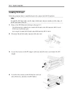
Remove the CPU/IO module referring to the page 8-12.
The following steps explain how to install a PCI board on the PCI board slot (PCI-X slot 2,
PCI-X slot 3) of the riser card.
Go to step 10 to install a PCI board on the PCI board slot (PCI-X slot 1).
2.
Disconnect the cable from the connector of the riser card.
3.
Loose a fixed screws on the PCI stopper on the rear side of the device, and remove the PCI
stopper.
4.
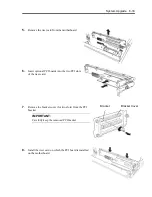
Loose the 3 fixed screws on the PCI bracket on the rear
side of the device, and remove the PCI bracket.
Summary of Contents for EXP320J
Page 12: ... THIS PAGE IS INTENTIONALLY LEFT BLANK ...
Page 25: ...xiii APPENDIX A SPECIFICATIONS A 1 APPENDIX B I O PORT ADDRESSES B 1 ...
Page 26: ...xiv THIS PAGE IS INTENTIONALLY LEFT BLANK ...
Page 28: ...1 2 Precautions for Use 使用上的注意 本章包含著對服務器恰當安全的操作必要的信息 ...
Page 54: ...1 28 Precautions for Use This page is intentionally left blank ...
Page 64: ...2 10 General Description Rear View ...
Page 68: ...2 14 General Description CPU IO Module CPU IO module ...
Page 88: ...2 34 General Description This page is intentionally left blank ...
Page 100: ...3 12 Windows Setup and Operation 3 Confirm that RDR of the disk is cancelled ...
Page 218: ...4 92 System Configuration This page is intentionally left blank ...
Page 390: ...5 172 Installing and Using Utilities This page is intentionally left blank ...
Page 408: ...6 18 Maintenance 3 Stop of PCI module 1 4 Start of PCI module 1 ...
Page 410: ...6 20 Maintenance This page is intentionally left blank ...
Page 454: ...7 44 Troubleshooting This page is intentionally left blank ...
Page 485: ...System Upgrade 8 31 board must not be mixed with N8804 005 or N8803 035 ...
Page 500: ......
Page 503: ......


