


3-62
POST Diagnostics
•
Power Status LED - This White LED is used to illuminate the NCR Logo on the bezel
to indicate that the system is on. In addition, this LED blinks when the system is in
S3 suspend mode.
•
LAN Link - This Green LED lights to indicate that the system is attached to a LAN. It
stays on whenever the LAN is present, even if the unit is powered off. This LED also
flashes to indicate LAN activity.
•
HDD Activity - This Green LED lights whenever there is activity to the hard drives.
•
Diagnostic LEDs (A-F) - These six Red LEDs are used to indicate various failure
modes of the system, primarily when the system fails to boot. These LEDS are
located behind the Front Base Cover, making them visible only when they are lit.
•
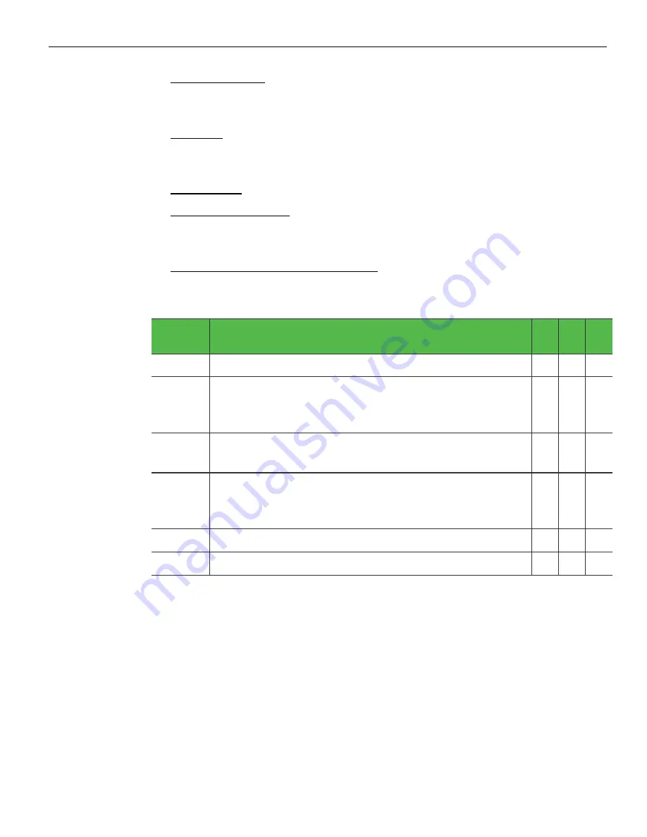
Power On Self Test (POST) Error (A-C): These three LEDS Flash during boot-up. If
boot fails, different combinations of LEDs indicate the point where POST failed to
aid in troubleshooting.
BIOS
Checkpoint
Description
A
B
C
Normal Operating condition after proper boot
OFF OFF OFF
D1
Keyboard Controller BAT test. Check if waking from power
management suspend state. Save power on CPUID value in
scratch CMOS.
OFF OFF ON
D4
Test Base 512kb memory. Adjust policies and cache first
8MB. Set stack. (Indicates Bad DIMM)
OFF ON OFF
04
Verify CMOS and update if necessary. Initialize data
variables. Also indicates that SATA device is not initializing.
(Indicates SATA Failure)
OFF ON ON
0A
Initialize keyboard controller
ON OFF OFF
Indicates that there is no memory detected in system.
ON ON ON
•
Temperature Warning (D): Lights when temperature threshold is exceeded and CPU
is throttling to prevent overheating. System performance may be affected during
throttling.
•
CPU Voltage Bad (E): Lights if CPU is not receiving adequate power to boot the
system (Check power supply and internal connection).
•
Power Supply Bad (F): Lit when power supply is not providing proper voltage to
internal connections, including powered serial ports. Isolates failure to internal
power supply. A, D, E, and F LEDs illuminate in this case.
Summary of Contents for RealPOS 72XRT POS
Page 1: ...USER GUIDE NCR RealPOS 72XRT POS 7616 Release 1 1 B005 0000 2228 Issue C...
Page 31: ...Product Overview 1 19 Additional peripheral connectors are located under the Customer Display...
Page 52: ...1 40...
Page 72: ...2 60...
Page 82: ...4 70 Touch Screen Calibration Do NOT get your hand and other fingers too close to the bezel...
Page 104: ...6 92...
Page 138: ...8 126...
Page 144: ...9 132 2x20 Customer Display Interface CP437...
Page 145: ...2x20 Customer Display Interface 9 133 CP858...
Page 146: ...9 134 2x20 Customer Display Interface CP866...
Page 147: ...2x20 Customer Display Interface 9 135 CP932...
Page 148: ...9 136...
Page 176: ...12 164...
Page 192: ...13 180...


