background image

Chapter 3:  BIOS Setup 3-39

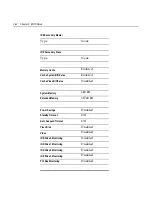
Boot Menu Options

 Item Specific Help

Removable Devices
+Hard Drive
ATAPI CD-ROM Drive
Intel ® Boot Agent Version ######

System Boot Sequence

The System Boot Sequence is a list of devices the terminal uses to boot
the system. To change the sequence of the devices:
1.


<ENTER> Expands or collapses devices using a + or _.

2.


<Ctrl + ENTER> Expands all.

3.


<Shift + 1> Enables or disables a device.

4.


<+> and <-> moves the device up and down.

Main

Advanced

Security

Power

Boot

Exit

PhoenixBIOS Setup Utility

Boot

Summary of Contents for 7460

Page 1: ...NCR 7460 Retail Terminal Release 1 2 Hardware User s Guide B005 0000 1280 Issue D...

Page 2: ...res functions and operations described herein may not be marketed by NCR in all parts of the world In some instances photographs are of equipment prototypes Therefore before using this document consul...

Page 3: ...Attention Le cordon d alimentation est utilis comme interrupteur g n ral La prise de courant doit tre situ e ou install e proximit du mat riel et tre facile d acc s Warning DO NOT connect or disconnec...

Page 4: ...he country of installation UL CSA TUV VDE or those which are recommended by NCR Corporation Environmental Consciousness NCR is demonstrating its concern for the environment by designing an intelligent...

Page 5: ...riptions 1 7 Processor Board 1 7 Processor Chip Set 1 7 Video Subsystem 1 7 Ethernet 10 100Base T LAN Communications 1 8 Universal Serial Bus 1 9 Serial Ports 1 9 Hardware Monitor 1 10 Mini PCI Expans...

Page 6: ...splay1 23 Other Integrated Devices and Indicators 1 24 Hard Disk Drive 1 24 Power Status LED 1 24 LAN Status LEDs 1 25 Power Supply 1 25 Chapter 2 Hardware Installation Introduction 2 1 Installation S...

Page 7: ...2 20 Mini PCI 56KB Modem 7460 F210 2 21 Installing the Modem 2 21 Finalizing the Installation 2 22 Completing the OS Installation WinNT 2 22 Completing the OS Installation Win98 2 23 Completing the O...

Page 8: ...ed Chipset Control 3 24 PCI Configuration 3 25 System Monitors 3 28 Multiple ROM Menu 3 29 QuickBoot Mode 3 31 After Power Failure 3 31 Continuous POST 3 32 Boot menu retry 3 32 LCD contrast and LCD B...

Page 9: ...Installation Win2000 4 5 Completing the OS Installation WinNT 4 6 Completing the OS Installation Win98 4 6 Completing the OS Installation Win95 4 7 Completing the OS Installation DOS 4 7 Gold Disk Co...

Page 10: ...5 1 Prerequisites 5 1 Updating Procedures 5 2 BIOS Crisis Recovery 5 3 Recovery Procedures 5 5 Cable Connector Pin Out Information 5 7 Chapter 6 NCR 7460 2x20 Customer Display Introduction 6 1 Viewing...

Page 11: ...ix Revision Record Issue Date Remarks A Feb 01 First issue B Jun 01 Add Peripherals Printers Cash Drawers C Oct 01 Update BIOS information D Jan 02 Added BIOS Crisis Recovery procedures...

Page 12: ...on interference caused by unauthorized modification of this equipment or the substitution or attachment of connecting cables and equipment other than those specified by NCR The correction of interfere...

Page 13: ...ration 1700 South Patterson Boulevard Dayton OH 45479 USA declares that the equipment specified above conforms to the referenced EU Directives and Harmonized Standards EU Directive Harmonized Standard...

Page 14: ...xii...

Page 15: ...an integrated compact cabinet the 7460 supports a complete set of peripherals The major hardware features of the 7460 are a flat panel display with touch screen input and LAN connectivity and magneti...

Page 16: ...1 2 Chapter 1 Product Overview Serial Number Labels 7460 18821 18866 NCR Corp Model 7460 01 S N 35012156...

Page 17: ...wo USB type A ports PS 2 keyboard port External VGA display port This does not allow different information on each display If you use an external display you get the same screen that you do on the ope...

Page 18: ...7892 Hand held Scanner Customer displays Integrated 2x20 Remote 2x20 32 MB flash disk Cash drawers 2189 Cash Drawer modular 2113 Cash Drawer modular 7454 K005 Mid range Cash Drawer modular 7460 Printe...

Page 19: ...isk flash disk or server storage Removable media e g a flex disk LAN communication to an NT server via standard protocols SLP terminal loading Local storage and TCP IP networking Keylock for security...

Page 20: ...Signature Capture RS 232 Peripherals 5945 Electronic Payment Terminal Transaction Printers Parallel Serial PS 2 KBD 7158 7194 7892 Bi modal Presentation Scanner 2189 DVI Cash Drawer RS 232 Keyboard 59...

Page 21: ...pabilities for optional features and future requirements ISA PCI bus and USB Video Subsystem The video subsystem supports the following LCD types 12 1 active matrix TFT 800x600 with 64 k colors Suppor...

Page 22: ...from Microsoft s web site When the platform is in the Soft OFF state refer to the Power Management section receipt of a Wakeup Packet on the LAN can return the system to the ON state if this feature...

Page 23: ...Link Integrity signal to become valid Universal Serial Bus Two USB Type A ports are provided on the terminal USB Host Controller support is provided in hardware on the processor board Note USB periphe...

Page 24: ...support optional features IDE Header A standard IDE header is provided to support the 3 5 inch hard disk drive Touch Screen Controller The MicroTouch Excalibur chip is used to interface the touch pan...

Page 25: ...our three with 12 V power PS 2 Keyboard Parallel Port MSR Cash Drawer 20 pin high density RS 232 Conversion connector S Video Flash Disk 32 MB flash disks provide non volatile storage that is addition...

Page 26: ...e The logic controls the following features Flash Disk Interface Cash Drawer Support Cash Drawer Diagnostic Support Magnetic Stripe Reader Interface Touch Screen Interface MSR The MSR interface suppor...

Page 27: ...6 85 Hz 640x480x16bpp 64 k 85 Hz 640x480x24bpp 16 M 85 Hz 800x600x8bpp 256 85 Hz 800x600x16bpp 64 k 85 Hz 800x600x24bpp 16 M 85 Hz 1024x768x4bpp 16 85 Hz 1024x768x8bpp 256 85 Hz 1280x1024x8bpp 256 60...

Page 28: ...y and the run time BIOS occupies E4000h through FFFFFh in lower memory BIOS Upgrades Flash memory makes distributing BIOS upgrades easy A new version of the BIOS can be installed from the hard disk ne...

Page 29: ...rocessor System Management Mode SMM capabilities and also spinning down hard drives and turning off VESA DPMS compliant monitors During setup the user may select which DPMS mode Stand By Suspend Auto...

Page 30: ...for the LCD panel This board has a connector that plugs directly into the LCD panel LCD Backlight Inverter Module The backlight for the 7460 is contained on the LCD Adapter Board Touch Screen The Tou...

Page 31: ...Customer Display The NCR 7460 Integrated Customer Display supports two lines of twenty 5x7 characters 18892 Integrated Customer Display The 7460 Retail Terminal also supports the NCR 5972 1000 Vacuum...

Page 32: ...gnetic Stripe Reader A single 3 track analog Magnetic Stripe Reader MSR is available as a feature supporting ISO format cards When the MSR is not desired a filler piece for the MSR section is included...

Page 33: ...phics printing It offers direct thermal printing in a receipt station The NCR 7194 can connect through a USB port or a serial port 16437 7158 Printer The 7158 Printer is extremely fast quiet and relia...

Page 34: ...receipt station It receives its power from an external power supply can be connected through a USB or serial port and has a connector for cash drawers 16437 7196 Printer The 7196 Printer is a high spe...

Page 35: ...tomer Display The 5972 1000 2x20 Customer Display is offered in two versions Vacuum Fluorescent Display VFD or Liquid Crystal Display LCD 15476 Vacuum Flourescent Display Liquid Crystal Display 15475...

Page 36: ...odels Integrated Remote Remote Tall Post Parallel I F support EIA 232 I F support Socket for 32K of PROM for additional character sets 7x9 pixel characters Diagnostics Character sets Code Page 850 Int...

Page 37: ...ay The NCR 5973 VFD Vacuum Fluorescent Display is an optional display device for the 7460 Retail Terminal The VFD is available in models that have a combination of Dark gray cabinetry Mounting configu...

Page 38: ...by notebook PCs Power Status LED The LED power indicator indicates that power is present The LED is green when the processor and BIOS are operating properly The LED is located on the right side of th...

Page 39: ...spills or other environmental hazards Note The power supply DOES NOT automatically sense the proper AC voltage therefore the switch on the back must be set prior to installation All power required to...

Page 40: ...1 26 Chapter 1 Product Overview...

Page 41: ...de to verify the correct hardware configuration The system is then configured and any communication cables are connected Note Verify the appropriate voltage setting prior to initial setup Only after i...

Page 42: ...ody before servicing the terminal If the power cord is replaced it must be replaced with the same type of cord with the protective shroud Do not route the power cord through openings with sharp edges...

Page 43: ...are located on the chassis behind the MSR Accessing the Cable Connectors and Routing Cables 1 Remove the MSR by elevating the unit and pulling down and out as illustrated Route Cables as necessary bet...

Page 44: ...tration identifies each of the cable connectors Refer to the sections following the illustration for specific instructions on installing each peripheral 18480 AC Voltage Selector AC Power Parallel Por...

Page 45: ...232 Connector on the printer located on the underside of the printer Printer Connector RS232 Cash Drawer Power Connector 17333 2 Connect the other end of the printer cable to a USB port or one of the...

Page 46: ...Connector Power Connector Cash Drawer Connector 2 Connect the other end of the printer cable to a USB port or one of the RS 232 non powered ports on the terminal 3 Connect the Power Brick cable to the...

Page 47: ...wiring between the locations desired for the terminal and the printer The ends of the cable should be within 3 meters 10 feet of the devices for the drop cables to reach Note Use CAT 1 two twisted pai...

Page 48: ...modems must be used with the appropriate NCR cables 7194 Printer 497 0411815 The modems can not be used with a standard OS printer driver that does not support DTR DSR flow control such as generic te...

Page 49: ...allation 2 9 2 Connect the other end of the printer cable to one of the RS 232 non powered ports on the terminal 3 Connect the Power Brick cable to the Power Connector on the printer 4 Plug the Power...

Page 50: ...unting configuration is the same and appearance is similar 5972 1000 1100 Remote Customer Display 2x20 characters VFD and LCD 5973 International VFD Customer Display NCR 5972 1000 1100 Remote Customer...

Page 51: ...run on top of the surface 3 Secure the Mounting Plate with 4 screws provided 16258 Mounting Plate 4 Holes 0 40 mm 0 16 in Diameter 76 mm 3 in 4 Connect the 5972 Display Cable to the RS 232 Adapter Cab...

Page 52: ...wer Brick Plug the Power Brick into an AC outlet 5973 International VFD Customer Display 14528 4 Screws 1 Place the Display Mount on the desired surface within 4 meters 13 feet of the host terminal 2...

Page 53: ...Mounting Plate with 4 screws provided 16258 Mounting Plate 4 Holes 0 40 mm 0 16 in Diameter 76 mm 3 in 4 Connect the 5973 Parallel Cable to the Parallel port on the terminal Parallel Port Customer Di...

Page 54: ...onsiderations Tilt Mount terminal can be installed on a flat horizontal surface or a flat vertical surface 18443 Shown below is the Base Unit option without the Operator LCD The LCD Mount Access Cover...

Page 55: ...Chapter 2 Hardware Installation 2 15 Wall Mounting the 7460 The 7460 unit or the Operator Display can be installed on a flat vertical surface 18835 7460 Wall Mount Operator Display Mount...

Page 56: ...uds or with hardware of similar strength The recommended viewing height for the terminal is 1 2 m 48 from the floor 18825 Wall Mount Adapter Plate Wall Plate Release Lever 2 Install the Wall Mount Ada...

Page 57: ...tallation 2 17 Wall Mounting the LCD Operators Display To flush mount the Operators Display on a flat vertical surface use the K502 Flush Mount Bracket Kit 18832 Flush Mount Flush Mount w LCD cable pe...

Page 58: ...he wall drill a hole in the wall for the cable 18826 Wall Plate Wall Mount Adapter Plate Cable Routing Release Lever 2 Install the Wall Mounting Adapter Plate to the back of the Operator Display with...

Page 59: ...sh Drawer 1 Place the cash drawer in the desired location within cable length of the terminal 19111 2 Connect the cash drawer cable to the terminal cash drawer connector 19114 Cash Drawer Note The Cas...

Page 60: ...The terminal supports a 2 drawer configuration with a Y cable 1416 C372 0006 1 Place the cash drawer in the desired location within cable s length of the terminal 2 Connect the Y cable to the terminal...

Page 61: ...ibed in B005 0000 1338 NCR 7460 Retail Terminal Hardware Service Guide 18876 Connector Modem Cable Routing 2 Remove knockout in the chassis for the modem connector 3 Route the modem cable through chas...

Page 62: ...tomatically reboots when the image recovery is complete and starts the software installation This installation also installs most of the additional software and drivers that are included in the disk i...

Page 63: ...in98 on terminals on some early Processor Boards there are few differences in the procedure as follows a The terminal starts the Add New Hardware Wizard b For each device found permit Windows to searc...

Page 64: ...te the installation as follows 1 After the terminal reboots press Next at the Windows Setup screen 2 At the User Information screen enter the User information This can be done using a keyboard or you...

Page 65: ...labeled Read Only and then select OK h Open the boot ini file with Notepad It should have the following entries operating systems multi 0 disk 0 rdisk 0 partition 1 WINNT Windows NT Workstation Versi...

Page 66: ...uchware Control Panel Windows to calibrate the touch screen Microcal a Set the video resolution Go to the Tools menu Video Select 800 x 600 256 colors b Go to the Tools menu select Calibrate Touchware...

Page 67: ...e Tools menu Video Select 800 x 600 256 colors b Go to the Tools menu select Noise Check c Follow the instruction prompts Choose the frequency with the lowest noise level Touchware Control Panel a Go...

Page 68: ...ut of box failed hard disks with identical preloaded drives Once a system is successfully installed all disk contents are the responsibility of the customer The customer is responsible for restoring o...

Page 69: ...Apply power to the terminal 2 Press the F2 key when the message at the bottom of the screen prompts you to do so Note Setup can also be entered from the Boot Menu that is displayed when you press ESC...

Page 70: ...ory Settings To reset all values to their default settings for the current screen press F9 The terminal will automatically load BIOS default CMOS values for boot up To reset all BIOS settings to their...

Page 71: ...eyond 2030 To set the date and time perform the following steps 1 Move your cursor to the System Time option enter the desired value and press Tab or Enter to continue with the next field 2 Enter the...

Page 72: ...ars for the IDE drive Item Specific Help Type Auto LBA Format Total Sectors 8452080 Maximum Capacity 4327MB Multi Sector Transfers 16 sectors LBA Mode Control Enabled 32 Bit I O Disabled Transfer Mode...

Page 73: ...n Large Disk Access Mode DOS Local Bus IDE adapter Primary Advanced Chipset Control PCI Configuration System Monitors Multiple ROM Menu QuickBoot Mode Enabled After Power Failure Enabled Continuous PO...

Page 74: ...Installed OS option and press Enter 2 Select the appropriate operating system from the drop down menu Note An incorrect setting can cause some operating systems to display unexpected behavior Reset Co...

Page 75: ...ase C800 CBFF Disabled Cache Base CC00 CFFF Disabled Cache Base D000 D3FF Disabled Cache Base D400 D7FF Disabled Cache Base D800 DBFF Disabled Cache Base DC00 DFFF Disabled Cache Base E000 E3FF Disabl...

Page 76: ...ing of system BIOS area 1 Move the cursor to Cache System BIOS Area and press Enter 2 Select the desired setting from the drop down menu Cache Video BIOS area This option controls caching of the video...

Page 77: ...elect the desired setting from the drop down menu Uncached Memory is not cached Write Through Writes are cached and sent to the main memory at once Write Protect Writes are ignored Write Back Writes a...

Page 78: ...areas 1 Move the cursor to the desired Cache area and press Enter 2 Select the desired setting from the drop down menu Disabled This block is not cached USWC Caching Uncached Speculative Write Combin...

Page 79: ...Reset Configuration Data No Cache Memory PS 2 port Touchscreen I O Device Configuration Large Disk Access Mode DOS Local Bus IDE adapter Primary Advanced Chipset Control PCI Configuration System Monit...

Page 80: ...Enter Item Specific Help Installed O S Other Reset Configuration Data No Cache Memory I O Device Configuration Large Disk Access Mode DOS Local Bus IDE adapter Primary Advanced Chipset Control PCI Con...

Page 81: ...red Port Auto LPT 1 Enabled Mode ECP Base I O Address 378 Interrupt IRQ7 DMA Channel DMA1 Fdc On Lpt Auto Floppy disk Controller Disabled Serial Port C Enabled Base I O Address 3E8 Interrupt IRQ 10 Po...

Page 82: ...ting from the drop down menu Disabled No configuration Enabled User configuration Auto BIOS or OS chooses configuration OS Controlled displayed when controlled by OS Base I O address Serial Port A B U...

Page 83: ...Move the cursor to Interrupt and press Enter 2 Select the desired setting from the drop down menu Interrupt Serial Port B This option is used to set the Interrupt for serial port B 1 Move the cursor...

Page 84: ...setting from the drop down menu Auto Detect special cable and turn power on if present On Set the power on at all times Off Always leaves power off LPT x This option is used to configure Parallel Por...

Page 85: ...rop down menu Base I O address LPT 1 This option is used to set the base I O address for LPT 1 1 Move the cursor to Base I O address and press Enter 2 Select the desired setting from the drop down men...

Page 86: ...m the drop down menu Fdc on LPT Use this option to enable the primary floppy on LPT 1 1 Move the cursor to Fdc on LPT and press Enter 2 Select the desired setting from the drop down menu Floppy disk c...

Page 87: ...Move the cursor to Base I O address and press Enter 2 Select the desired setting from the drop down menu Interrupt Serial Port C This option is used to set the Interrupt for serial port C 1 Move the c...

Page 88: ...press Enter 2 Select the desired setting from the drop down menu Auto Detect special cable and turn power on if present On Set the power on at all times Off Always leaves power off Interrupt Serial P...

Page 89: ...n menu Base I O address LPT 2 This is used to set the base I O address for LPT 2 1 Move the cursor to Base I O address and press Enter 2 Select the desired setting from the drop down menu Interrupt LP...

Page 90: ...annel and press Enter 2 Select the desired setting from the drop down menu Disk On Chip Address Use this option to select the memory address range used for the Disk On Chip 1 Move the cursor to Disk O...

Page 91: ...red setting from the drop down menu Large Disk Access Mode Use this option to set the Large Disk Access Mode Note UNIX Novell NetWare or other operating systems select Other If you are installing new...

Page 92: ...adapter and press Enter 2 Select the desired setting from the drop down menu Advanced Chipset Control Move the cursor to Advanced Chipset Control and press Enter to access the submenu Video boot type...

Page 93: ...ended memory gap and press Enter 2 Select the desired setting from the drop down menu PCI Configuration Move the cursor to PCI Configuration and press Enter to access the submenu PCI Configuration Ite...

Page 94: ...press Enter 3 Select the desired setting from the drop down menu Select Reserved to reserve a specified block of upper memory for use by legacy ISA devices PCI PNP ISA IRQ Resource Exclusion This opt...

Page 95: ...evice cannot use IRQs already in use by ISA or EISA devices Use Auto Select only if no ISA or EISA legacy cards are installed 1 Move the cursor to the appropriate PCI IRQ Line 1 through 4 option and p...

Page 96: ...pset Control PCI Configuration System Monitors Multiple ROM Menu QuickBoot Mode Enabled After Power Failure Enabled Continuous POST Disabled Boot menu retry Keyboard LCD Contrast 32 LCD Brightness 64...

Page 97: ...o Cache Memory PS 2 Port No I O Device Configuration Large Disk Access Mode DOS Local Bus IDE adapter Primary Advanced Chipset Control PCI Configuration System Monitors Multiple ROM Menu QuickBoot Mod...

Page 98: ...M 9 Disabled Selectable ROM 10 Disabled Selectable ROM 11 Disabled Selectable ROM 12 Disabled Selectable ROM 13 Disabled Selectable ROM 14 Disabled Selectable ROM 15 Disabled Selectable ROM 16 Disable...

Page 99: ...nter 2 Select the desired setting from the drop down menu After Power Failure This option sets the mode of operation if an AC power loss occurs 1 Move the cursor to After Power Failure and press Enter...

Page 100: ...esired setting from the drop down menu Keyboard User must press a key before POST will retry booting from the devices in the boot menu Auto POST will loop continuously through the boot menu devices wi...

Page 101: ...d is not present To enter a password follow these steps Note The User Password cannot be set until after the Supervisor Password is set 1 Move the cursor to the Set Supervisor Password or Set User Pas...

Page 102: ...sword on Boot This option enables disables the password entry on boot Note User Password must also be set 1 Move the cursor to Password on Boot and press Enter 2 Select the desired setting from the dr...

Page 103: ...er management mode 1 Move the cursor to Power Savings and press Enter 2 Select the desired setting from the drop down menu Disabled power Management is turned off Customize user defined settings Maxim...

Page 104: ...Standby Timeout and press Enter 2 Select the desired setting from the drop down menu Auto Suspend Timeout Customized Mode Auto Suspend Timeout identifies the amount of time the system needs to be in...

Page 105: ...eout and press Enter 2 Select the desired setting from the drop down menu Resume On Time This option is used to enable the system to wake up at a specific time 1 Move the cursor to Resume On Time and...

Page 106: ...r to Resume On Time 2 To specify time use TAB SHIFT TAB or ENTER to select fields 00 00 00 Resume On Modem Ring This option enables the system to wake up when an incoming call is detected on your mode...

Page 107: ...Sequence The System Boot Sequence is a list of devices the terminal uses to boot the system To change the sequence of the devices 1 ENTER Expands or collapses devices using a or _ 2 Ctrl ENTER Expands...

Page 108: ...s to CMOS memory Exit Discarding Changes Exit without saving changed option values to CMOS memory Load Setup Defaults Load default value for all BIOS options Discard Changes Load previous values from...

Page 109: ...ically detected and the correct BIOS is automatically installed Main Values System Time variable System Date variable Legacy Diskette A Disabled IDE Primary Master Type Auto Cylinders 8944 Heads 15 Se...

Page 110: ...d Cache Video BIOS area Disabled System Memory 640 kB Extended Memory 31744 kB Power Savings Disabled Standby Timeout Off Auto Suspend Timeout Off Fixed Disk Disabled Video Disabled IDE Drive 0 Monito...

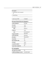
Page 111: ...ort A Auto Serial port B Auto Mode Normal Parallel port Auto Mode Bi directional Floppy disk controller Disabled Disk On Chip Address Disabled MSR Address DE00 DFFF Plug and Play No Reset Configuratio...

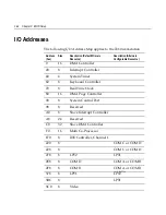
Page 112: ...upt Controller 40 4 System Timer 60 8 Keyboard Controller 70 8 Real Time Clock 80 16 DMA Page Controller 90 8 System Control Port 98 8 Reserved A0 8 Slave Interrupt Controller A8 24 Reserved C0 32 Sla...

Page 113: ...x Size Description Default Primary Resource Description Alternate Configurable Resource 3E8 8 COM C COM A or COM B 3F0 8 Floppy Drive 3F8 8 COM A 1800 8 IDE 1810 8 SM Bus 1820 8 USB 1840 8 Audio 1C00...

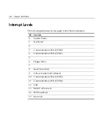
Page 114: ...0 workstation IRQ Description 0 System Timer 1 Keyboard 2 3 Communications Port COM 2 4 Communications Port COM 1 5 6 Floppy Drive 7 8 Real Time Clock 9 Video Audio LAN shared 10 Communications Port C...

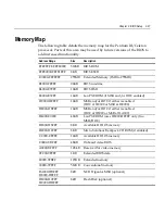
Page 115: ...bled DC000 DFFFF 16KB MSR and or DOC if either is enabled DOC at DC000 or MSR at DE000 D8000 DBFFF 16KB MSR and or DOC if either is enabled DOC at D8000 or MSR at DA000 D4000 E0000 48KB Lan PXE ROM us...

Page 116: ...3 48 Chapter 3 BIOS Setup...

Page 117: ...that are necessary to run the CD ROM are temporarily installed during boot Prerequisites The following are required on the 7460 in order to perform a OS Recovery using a CD Bootable CD ROM drive 2336...

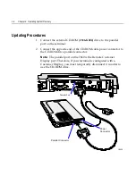
Page 118: ...the opposite end of the CD ROM cable power connector to the CD ROM drive parallel connector Note The parallel port on the 7460 is the Remote Customer Display port Therefore if your terminal is config...

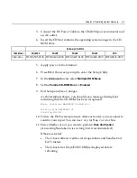
Page 119: ...ROM Menu 8 Set the Parallel CD ROM Boot to Enabled 9 Exit Setup and Save Changes As the terminal reboots you should see a message during boot indicating that the CD ROM has been recognized Micro Solu...

Page 120: ...on reboot 12 Select which type of recovery you want to perform from the next menu normally option 1 1 Redo entire disk with the first partition the same size 2 Redo the first OS partition 3 Redo the...

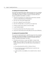
Page 121: ...Enter the User Name and Organization 3 Enter the Computer Name for the client 4 Enter the Administrator s Account Password optional 5 When prompted press Finish to reboot the client 6 Login when prom...

Page 122: ...ent 6 Log in when prompted 7 Press Next at the Found New Hardware wizard 8 Open the Control Panel and run the MicroTouch screen calibration Completing the OS Installation Win98 The system automaticall...

Page 123: ...installation This installation also installs most of the additional software and drivers that are included in the disk image Complete the installation as follows 1 After the terminal reboots press Nex...

Page 124: ...kstation or kiosk preloaded with a Microsoft operating system the application provider must follow certain license agreement guidelines Listed below are some of the major points of Microsoft s Embedde...

Page 125: ...ge drivers installed version 6 03 MicroTouch TouchWare installed version 5 6F Beta Windows Installer installed version 1 1 NCRSYSM driver installed version 2 01 01 003 10 Backpack CD Rom drivers avail...

Page 126: ...er installed version 4 03 1381 2687 Intel R 82559 Fast Ethernet LAN driver installed version 5 00 66 0000 MicroTouch TouchWare installed version 5 6F Beta Windows Installer installed version 1 1 NCRSY...

Page 127: ...el R 82810 DC100 Video drivers installed version 4 12 01 2687 Intel R 82559 Fast Ethernet LAN drivers installed version 5 00 67 0000 MicroTouch TouchWare installed version 5 6F Beta Windows Installer...

Page 128: ...12 01 2687 Intel R 82559 Fast Ethernet LAN driver installed version 5 00 66 0000 MicroTouch TouchWare installed version 5 6F Beta Windows Installer Version 1 1 installed NCRSYSM driver installed vers...

Page 129: ...the DOS screen prompts After each entry you are asked to confirm your input You can use 1 or y for Yes 2 or n for No 3 Enter No at the Disk verification question 4 Select which type of recovery you wa...

Page 130: ...e of the 2nd partition O S 2nd Partition Format 2nd Partition Size NT NTFS Fill the remaining drive space Win2000 NTFS Fill the remaining drive space Win98 FAT32 Fill the remaining drive space Win95 F...

Page 131: ...etwork connection Refer to the NCR FitClient Software User s Guide for information about that procedure Crisis Recovery In the event the BIOS becomes corrupt such as the result of a power failure duri...

Page 132: ...port on the terminal Parallel Connector Power Connector Parallel Port 18532 2 Connect the Power Cable to the CD ROM power connector and an AC outlet 3 Insert the BIOS CD in the CD ROM drive NCR BIOS a...

Page 133: ...umber information If the program detects invalid information in the current BIOS or if you are replacing the processor board there is not model serial number information in the BIOS Important Model Se...

Page 134: ...rare occurrence and should not be confused with other hardware errors that cause a no video state This procedure is not intended to be used for changing or upgrading an operational BIOS Required Hard...

Page 135: ...onnect the two machines with the RS 232 cable Use COM Port 1 on both machines 19508 NCR 7460 PC RS 232 Cable 3 Boot the PC in the DOS mode with CD ROM support Note The PC must be running in the DOS mo...

Page 136: ...4 7453 5 7455 6 7460 7 7451 8 7456 6 Enter A blue screen displays as the program runs showing the program progress followed by a green screen indicating a successful load PhoenixPhlash Status PRESS AN...

Page 137: ...ion Parallel Dongle 19513 25 Pin D shell Receptacle Viewed from wiring side 25 24 23 22 21 20 19 18 17 16 15 14 13 12 11 10 9 8 7 5 4 3 2 1 6 RS 232 Cable 19512 1 2 3 4 5 6 7 8 1 2 3 4 5 6 7 8 P1 P2 9...

Page 138: ...5 8 Chapter 5 BIOS Updating Procedures...

Page 139: ...in 2 rows of 20 characters Each character is a 5x7 dot matrix 16674a 1 2 3 20 Diagnostics Power Up Diagnostics occur soon after the hardware reset circuitry is released or when a Reset Display command...

Page 140: ...display hardware interface is similar to a standard parallel port interface The display is logically connected to LPT2 Standard parallel port drivers cannot be used since the standard hardware connec...

Page 141: ...ol 0 0 0 0 0 0 1 D C B Set Display D cursor C and blinking of cursor B on off control bit 37 s Cursor or Display Shift 0 0 0 0 0 1 S C R L X X Set interface data length DL 4 bit 8 bit numbers of displ...

Page 142: ...6 4 Chapter 6 NCR 7460 2x20 Customer Display Character Map...

Page 143: ...02 M only have 5 x 8 dots so the last two rows of characters beginning at 11100000 cannot be displayed correctly These last two rows consist of symbols that are not typically used If one of these char...

Page 144: ......

Page 145: ...1416 C266 0152 497 0409379 7193 RS 232 50 9 pin female to 9 pin female 1416 C337 0010 497 0407427 RS 232 interface integrated 1416 C337 0040 497 0407429 RS 232 interface remote 1416 C337 0152 497 0407...

Page 146: ...A 2 Appendix A Cables...

Page 147: ...COIN DISPENSER BASE UNIT RS 232 2336 K024 V001 497 0416286 CD ROM w Parallel Cable International Power 2756 K152 V002 497 0409426 KDS Cable 2756 K800 V001 497 0411009 KIT Wall Mount 2756 K801 V001 497...

Page 148: ...301 V001 497 0411975 Power supply 55 W 7158 K330 V001 497 0411974 Supply Power 55W w US Power Cord 7194 K260 V001 497 0411924 Wall Mount Kit 7453 K007 V001 497 0414767 Till with lid and lock 7454 K005...

Page 149: ...Appendix B Kits 2 3 Kit Number Part Number Description 7460 K533 V001 497 0419707 Base unit wall mount 7460 K800 V001 497 0420615 1 44 MBExternal Flex Disk Drive...

Page 150: ......

Page 151: ...6 1 command descriptions 6 2 diagnostics 6 1 E Ethernet 10 100Base T 1 8 F Features kits CD ROM drive 2336 K024 2 21 Flash disk 1 11 Flash disk interface 1 12 FLASH memory implementation 1 14 G Graph...

Page 152: ...on 2 5 Printers 1 19 Processor board Connector descriptions 1 11 Description 1 7 Features 1 3 Processor chip set 1 7 R Remote customer display Installation 2 10 Resolutions supported 1 13 S serial mou...

Page 153: ......
Reviews: