


XR12 Installation Manual
Control and monitoring
Issue 3.0 2009-07-15
Page 9-9
•
TB1-14 (-):
EXCITER A
terminal. Causes a changeover to select exciter A as the main exciter.
Setting is saved in current preset. Provide an active pulse to select this exciter.
•
TB1-16 (-):
EXCITER B
terminal. Causes a changeover to select exciter B as the main exciter.
Setting is saved in current preset. Provide an active pulse to select this exciter.
•
TB1-10 (-):
POWER INCREASE
terminal. Increases the power level of the current preset.
Send an active pulse to increase the power slightly, or send a signal of greater duration to
continue increasing the power.
•
TB1-12 (-):
POWER DECREASE
terminal. Decreases the power level of the current preset.
Send an active pulse to decrease the power slightly, or send a signal of greater duration to
continue decreasing the power.
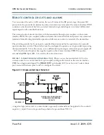
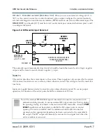
Remote status and alarm indications
Outputs that indicate the status of operator controlled circuits are available on connectors J2 and J3
on the remote interface PWB. A switching device for each alarm output provides current-sink-to-
ground when a logic true condition exists.
The switching circuit provides an open collector for a logic false condition and has no influence on
the external monitoring circuit.
The following outputs are available:
Note: All outputs are active low.
•
J3-18:
Exciter Changeover
. See
.
•
J2-24:
Preset Scheduler On Status
.
•
J3-21:
Auto Exciter Status
. Indicates if the current preset allows auto exciter changeover in the
event of failures. (Set from the GUI only.)
•
J3-20:
Memory Battery Alarm
“Low backup battery” on page 9-5
.
•
J3-19:
RF Overcurrent Alarm
•
J2-23:
Exciter B Status
. Indicates which exciter is presently active.
•
J3-15:
LVPS Fail
•
J3-14:
Exciter Fail
.
Summary of Contents for XR12
Page 2: ......
Page 4: ......
Page 16: ...XR12 Installation Manual Page xvi Issue 3 0 2009 07 15...
Page 22: ...XR12 Installation Manual Unpacking and positioning Page 2 4 Issue 3 0 2009 07 15...
Page 26: ...XR12 Installation Manual Installing the power transformer Page 3 4 Issue 3 0 2009 07 15...
Page 36: ...XR12 Installation Manual Installing the RF connector Page 6 6 Issue 3 0 2009 07 15...
Page 48: ...XR12 Installation Manual Adjusting the spark gap Page 7 12 Issue 3 0 2009 07 15...
Page 78: ...XR12 Installation Manual Parts and tools Page 12 4 Issue 3 0 2009 07 15...
Page 91: ......


