XR12 Installation Manual
Pre-installation / Installation assistance
Page 13-2
Issue 3.0 2009-07-15
•
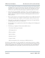
Ac power wiring for the transmitter has been installed and connected at the breaker panel or
the building’s service entrance. If local electrical codes allow Nautel personnel to connect the
transmitter to the ac supply, using the customer's cable, that task is included in this service.
Otherwise, the customer must ensure that an approved electrician is present for this task.
•
The customer has prepared the RF coaxial cable – used to connect the transmitter to the
antenna – and installed the required connector. The customer has also installed the RF coax-
ial cable in place and connected it to the antenna, while leaving the transmitter end of the
cable unconnected.
•
Where required, all remote control and monitoring cables have been installed and connected
to the station equipment (e.g., modulation monitor, frequency monitor, and power meter).
•
The site has been made ready for the equipment, and adequate protection against lightning
and lightning-induced transients has been provided.
•
The transmitter has been unpacked, closely checked for any damage caused by shipping, and
then assembled.
•
The following test equipment has been made available at the site:
– Two-channel oscilloscope (with probes)
– Audio signal generator
– Distortion analyzer
– Spectrum analyzer
– Modulation monitor
– Frequency counter
– 50
Ω
test load (rated for 150% of carrier power, VSWR less than 1.1:1)
Nautel’s service representative takes full responsibility for commissioning the transmitter, validating
all external interfaces (i.e., the ac supply, RF output, remote control and monitoring equipment) and
checking out the equipment prior to activation. The service representative turns on the transmitter,
performs all adjustments and set-up procedures, and carries out
proof of performance
tests at the site.
Summary of Contents for XR12
Page 2: ......
Page 4: ......
Page 16: ...XR12 Installation Manual Page xvi Issue 3 0 2009 07 15...
Page 22: ...XR12 Installation Manual Unpacking and positioning Page 2 4 Issue 3 0 2009 07 15...
Page 26: ...XR12 Installation Manual Installing the power transformer Page 3 4 Issue 3 0 2009 07 15...
Page 36: ...XR12 Installation Manual Installing the RF connector Page 6 6 Issue 3 0 2009 07 15...
Page 48: ...XR12 Installation Manual Adjusting the spark gap Page 7 12 Issue 3 0 2009 07 15...
Page 78: ...XR12 Installation Manual Parts and tools Page 12 4 Issue 3 0 2009 07 15...
Page 91: ......

