


XR12 Installation Manual
Commissioning tasks
Issue 3.0 2009-07-15
Page 11-3
Commissioning
Turning on the transmitter
1. Terminate the transmitter's RF output into a precision, 50
Ω
, resistive dummy load that is
able to dissipate the RF power being applied to it: 12 kW carrier, 18 kW total required.
2. Verify that all panels are installed, and ensure that their attaching hardware is firmly
tightened.
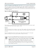
3. Simulate the closing of all external interlocks. This requires a short circuit between TB1-1
and TB1-2 of the remote interface PWB. Ensure all networks connected to the transmitter’s
RF output are properly covered.
4. In lieu of normal station programming, connect an audio signal generator, preset to 1000 Hz
at a zero output level (turned off), between TB2-1 (+) and TB2-3 (-) on the remote interface
PWB.
5. Switch on the ac power at the service entrance to turn on the transmitter.
6. Look through the window on the left side of the transmitter’s lower rear panel (as seen from
the back). Verify that all four power status LEDs are on.
7. Check the alarm and status indicators (the front panel and GUI). See the
XR12 Operating and
Maintenance Guide
.
8. Check the output of the B+ power supply on the GUI. The voltage should be between 320
and 340 V dc.
9. Check the output of the 5, 15, and 24 V power supplies on the GUI.
10. Select
Local
control.
WARNING:
If a jumper is placed between interlock inputs TB1-1/TB1-2 on the
remote interface pwb, safety features controlled by the external
interlocks will be disabled. A fail safe method of alerting personnel to
this fact should be implemented. Voltages which are dangerous to life
will be present on the RF output stages and the antenna system if the
transmitter is turned on.
Summary of Contents for XR12
Page 2: ......
Page 4: ......
Page 16: ...XR12 Installation Manual Page xvi Issue 3 0 2009 07 15...
Page 22: ...XR12 Installation Manual Unpacking and positioning Page 2 4 Issue 3 0 2009 07 15...
Page 26: ...XR12 Installation Manual Installing the power transformer Page 3 4 Issue 3 0 2009 07 15...
Page 36: ...XR12 Installation Manual Installing the RF connector Page 6 6 Issue 3 0 2009 07 15...
Page 48: ...XR12 Installation Manual Adjusting the spark gap Page 7 12 Issue 3 0 2009 07 15...
Page 78: ...XR12 Installation Manual Parts and tools Page 12 4 Issue 3 0 2009 07 15...
Page 91: ......