


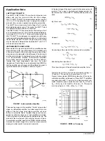

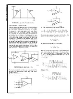


Bandpass Filter
The center frequency and Quality Factor for all of these filters
is the same. The values can be calculated in the following
manner:
A design example is shown here:
Designing a bandpass filter with center frequency of 10kHz
and Quality Factor of 5.5
To do this, first consider the Quality Factor. It is best to pick
convenient values for the capacitors. C
2
= C
3
= 1000pF. Also,
choose R
1
= R
4
= 30k
Ω
. Now values of R
5
and R
6
need to be
calculated. With the chosen values for the capacitors and re-
sistors, Q reduces to:
or
R
5
= 10R
6
R
6
= 1.5k
Ω
R
5
= 15k
Ω
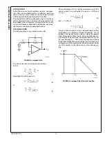
Also, for f = 10kHz, the center frequency is
ω
c
= 2π
f =
62.8kHz.
Using the expressions above, the appropriate resistor values
will be R
2
= R
3
= 16k
Ω.
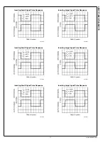
The following graphs show the transfer function of each of the
filters. The DC gain of this circuit is:
20039690
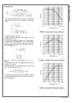
The frequency responses of each stage of the state variable
active filter when implemented with the LMV774 are shown in
the following figures:
20039691
FIGURE 10. Lowpass Filter Frequency Response
20039692
FIGURE 11. Bandpass Filter Frequency Response
20039693
FIGURE 12. Highpass Filter Frequency Response
17
www.national.com
LMV771/LMV772/LMV774


