


20039662
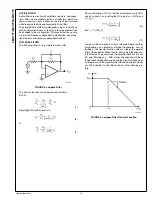
FIGURE 8. Bandpass filter Transfer Function
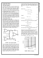
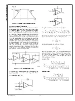
STATE VARIABLE ACTIVE FILTER
State variable active filters are circuits that can simultane-
ously represent high pass, band pass, and low pass filters.
The state variable active filter uses three separate amplifiers
to achieve this task. A typical state variable active filter is
shown in Figure 9. The first amplifier in the circuit is connected
as a gain stage. The second and third amplifiers are connect-
ed as integrators, which means they behave as low pass
filters. The feedback path from the output of the third amplifier
to the first amplifier enables this low frequency signal to be
fed back with a finite and fairly low closed loop gain. This is
while the high frequency signal on the input is still gained up
by the open loop gain of the 1st amplifier. This makes the first
amplifier a high pass filter. The high pass signal is then fed
into a low pass filter. The outcome is a band pass signal,
meaning the second amplifier is a band pass filter. This signal
is then fed into the third amplifiers input and so, the third am-
plifier behaves as a simple low pass filter.
20039674
FIGURE 9. State Variable Active Filter
The transfer function of each filter needs to be calculated. The
derivations will be more trivial if each stage of the filter is
shown on its own.
The three components are:
20039680
20039681
For A
1
the relationship between input and output is:
This relationship depends on the output of all the filters. The
input-output relationship for A
2
can be expressed as:
And finally this relationship for A
3
is as follows:
Re-arranging these equations, one can find the relationship
between V
O
and V
IN
(transfer function of the lowpass filter),
V
O1
and V
IN
(transfer function of the highpass filter), and
V
O2
and V
IN
(transfer function of the bandpass filter) These
relationships are as follows:
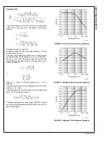
Lowpass Filter
Highpass Filter
www.national.com
16
LMV771/LMV772/LMV774


