


Figure 5.
Basic NI-RFSG Block Diagram
7.
Right-click the resource name input on the niRFSG Initialize VI, and select
Create
»
Control
to create a front panel control where you specify the NI RF signal generator
device name.
Figure 6.
Resource Name Input on the niRFSG Initialize VI
8.
Right-click the frequency (Hz) input on the niRFSG Configure RF VI, and select
Create
»
Control
.
9.
Right-click the power level (dBm) input on the niRFSG Configure RF VI, and select
Create
»
Control
.
10. Display the VI front panel by clicking it or by selecting
Window
»
Show Front Panel
.
11. In the VI front panel
power level (dBm)
control, enter
0
. In the
frequency (Hz)
control,
enter
100M
(100 MHz).
12. In the VI front panel
resource name
control, enter the NI 5650/5651/5652 device name
that you specified in MAX.
Adding a While Loop
Add a While Loop to continuously generate the signal and check the generation status until
you click the
Stop
button.
1.
Display the VI block diagram, and select the While Loop on the Structures palette.
Tip
You can use the
Search
button on the Functions palette to find the
Structures palette.
2.
Enclose the niRFSG Check Generation Status VI in the While Loop, as shown in the
following figure.
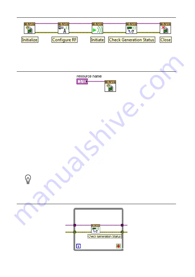
Figure 7.
The niRFSG Check Generation Status VI Enclosed in the While Loop
NI PXIe-5650/5651/5652 Getting Started Guide
|
© National Instruments
|
13


