


Installing the NI 5650/5651/5652
Caution
To prevent damage to the device caused by ESD or contamination, handle
the device using the edges or the metal bracket.
You must install NI-RFSG before installing the hardware.
Before you install the hardware, refer to the guidelines in the
Maintain Forced-Air Cooling
Note to Users
included with the module to ensure that the chassis can cool the device
effectively.
1.
Ensure the AC power source is connected to the chassis before installing the module. The
AC power cord grounds the chassis and protects it from electrical damage while you
install the module.
2.
Power off the chassis.
3.
Inspect the slot pins on the chassis backplane for any bends or damage prior to
installation. Do not install a module if the backplane is damaged.
4.
Remove the black plastic connectors from all the captive screws on the module front
panel.
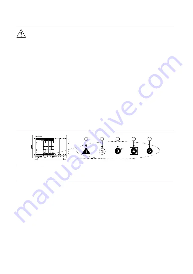
5.
Identify a supported slot in the chassis. The following figure shows the symbols that
indicate the slot types.
Figure 2.
Chassis Compatibility Symbols
NI PXIe-1062Q
1
2
3
4
5
1. PXI Express System Controller Slot
2. PXI Peripheral Slot
3. PXI Express Hybrid Peripheral Slot
4. PXI Express System Timing Slot
5. PXI Express Peripheral Slot
NI 5650/5651/5652 modules can be placed in PXI Express peripheral slots or
PXI Express Hybrid peripheral slots.
6.
Touch any metal part of the chassis to discharge static electricity.
7.
Ensure that the ejector handle is in the unlatched (downward) position.
8.
Place the module edges into the module guides at the top and bottom of the chassis. Slide
the device into the slot until it is fully inserted.
NI PXIe-5650/5651/5652 Getting Started Guide
|
© National Instruments
|
5