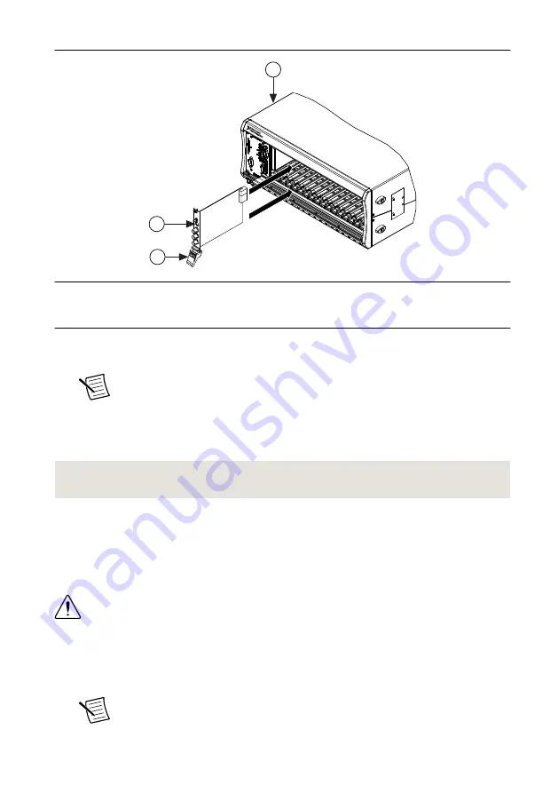
Figure 3.
Module Installation
2
3
NI PXIe-1075
1
1. Chassis
2. Hardware Module
3. Ejector Handle in Down (Unlatched) Position
9.
Latch the module in place by pulling up on the ejector handle.
10. Secure the device front panel to the chassis using the front-panel mounting screws.
Note
Tightening the top and bottom mounting screws increases mechanical
stability and also electrically connects the front panel to the chassis, which can
improve the signal quality and electromagnetic performance.
11. Cover all empty slots using filler panels or slot blockers to maximize cooling air flow.
12. Power on the chassis.
Related Information
on page 4
Installing the SMA Cables
To use the NI 5650/5651/5652 with other devices, you must make connections using SMA
cables. For best results when connecting signals to the NI 5650/5651/5652 front panel SMA
connectors, use shielded low-loss coaxial cables.
Caution
The signal pins of this product's input/output ports can be damaged if
subjected to ESD. To prevent damage, remove power from the product before
connecting cables and employ industry-standard ESD prevention measures during
installation, maintenance, and operation.
1.
Connect the cable center pin on the SMA cable to the SMA connector on the appropriate
device.
Note
Ensure that the SMA cable center pins properly align with the SMA
connectors to avoid bending the cable pins or damaging the front panel
6
|
ni.com
|
NI PXIe-5650/5651/5652 Getting Started Guide


