background image

PXIe-4310 and TB-4310 (10V)/TB-4310 (600V) 

|

© National Instruments

|

11

Tip

Using an NI-DAQmx simulated device, you can test NI-DAQmx applications 

without installing hardware. Refer to the 

Create a Simulated Device

 section for 

instructions for creating NI-DAQmx simulated devices.
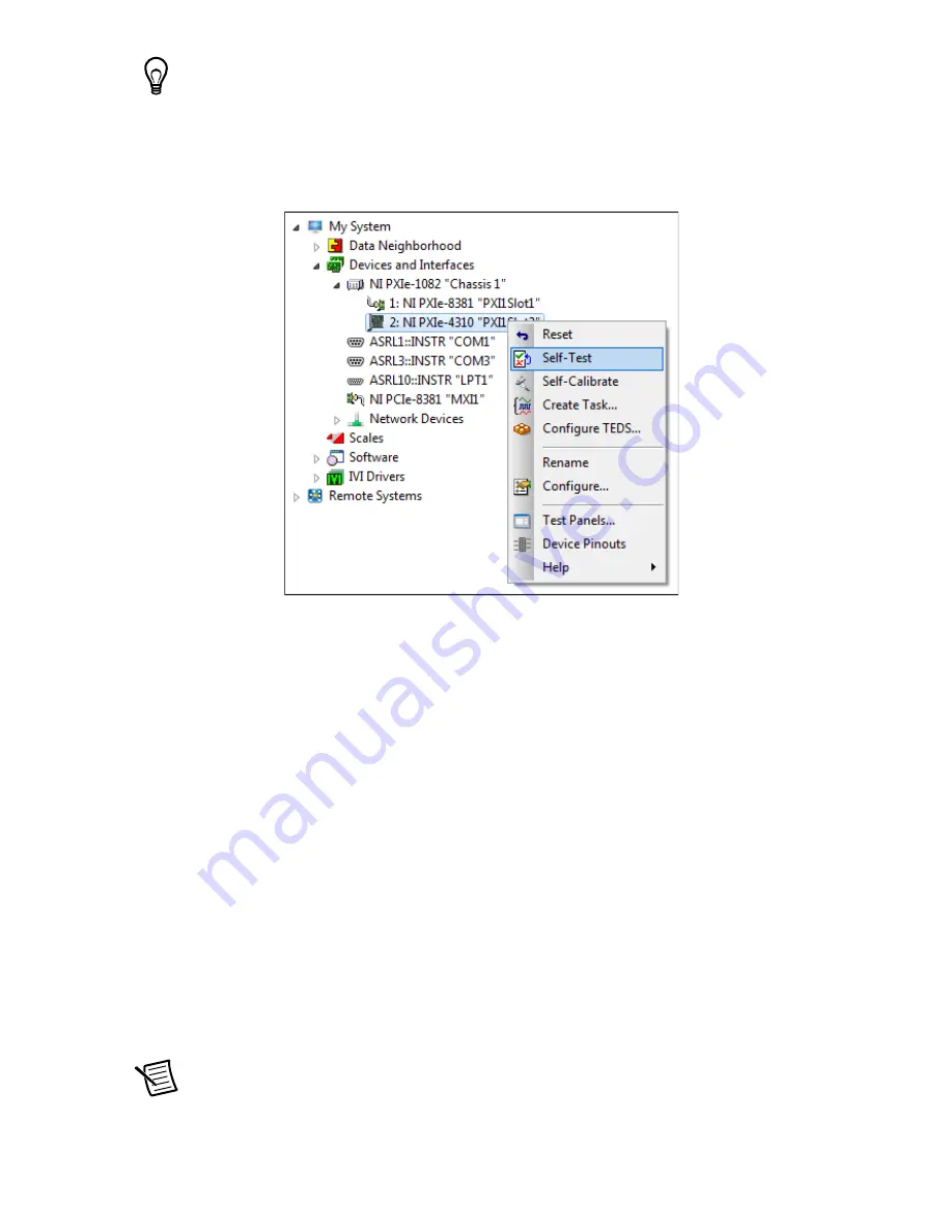
4.

Right-click the module name and select 

Self-Test

. When the self-test completes, a 

verification message appears. If an error occurs, refer to 

ni.com/support/daqmx

.

Device Self-Calibration

NI recommends that you self-calibrate your PXIe-4310 module after installation and whenever 
the ambient temperature changes. Self-calibration should be performed after the device has 
warmed up for the recommended time period. Refer to the device specifications to find your 
device warm-up time. This function measures the onboard reference voltage of the device and 
adjusts the self-calibration constants to account for any errors caused by short-term fluctuations 
in the environment.

You can initiate self-calibration using Measurement & Automation Explorer (MAX), by 
completing the following steps:
1.

Launch MAX.

2.

Select 

My System»Devices and Interfaces»

your device

.

3.

Initiate self-calibration using one of the following methods:

Select the PXIe-4310 in the MAX configuration tree and click the 

Self-Calibrate


button located on the MAX toolbar.

Right-click the name of the device in the MAX configuration tree and select 

Self-Calibrate

 from the drop-down menu.

Note

You can also programmatically self-calibrate your device with NI-DAQmx, 

as described in 

Device Calibration

 in the 

NI-DAQmx Help

 or the 

LabVIEW Help

.

Summary of Contents for PXIe-4310

Page 1: ...necting to other modules that could be damaged by the voltage present on the terminal block However you should only use these terminal blocks with their supported modules Caution Do not supply hazardo...

Page 2: ...Support and Services 24 Electromagnetic Compatibility Guidelines This product was tested and complies with the regulatory requirements and limits for electromagnetic compatibility EMC stated in the p...

Page 3: ...ifications provided by the manufacturer You are responsible for verifying the safety compliance of third party connectors and their usage according to the relevant standard s including UL and CSA in N...

Page 4: ...st supported in NI DAQmx 17 1 Note For detailed NI software version support refer to the NI DAQmx Readme Back up any applications before upgrading software or modifying the application Unpack and Inst...

Page 5: ...ssis Slot Type Symbol Location 5 Remove the filler panel and touch any metal part of the chassis to discharge static electricity 6 Place the module edges into the module guides at the top and bottom o...

Page 6: ...ut the terminal block being connected to the PXIe 4310 A terminal block is required to make connections to the module To connect signals to the TB 4310 10V TB 4310 600V refer to Figures 3 and 4 while...

Page 7: ...determine the function of the terminal The PXIe 4310 User Manual provides more detailed wiring information Make sure no exposed wire extends past the screw terminal Exposed wire increases the risk of...

Page 8: ...elding the signals 7 Reinstall the strain relief bar and tighten the strain relief screws 8 Use tie wraps to connect the shielded signal wires to the tie wrap holes for additional strain relief when n...

Page 9: ...rminal block 3 Tighten the mounting screw at the top of the terminal block to attach it to the module Note For safety purposes and to prevent damage to equipment when high voltages are present all PXI...

Page 10: ...ystem 2 Launch MAX 3 Expand Devices and Interfaces and expand the chassis in which the module is located to confirm that MAX detects the module and terminal block The terminal block should appear bene...

Page 11: ...Refer to the device specifications to find your device warm up time This function measures the onboard reference voltage of the device and adjusts the self calibration constants to account for any err...

Page 12: ...nd Tasks Refer to the NI DAQmx Help for complete information about channels and tasks Use the DAQ Assistant to configure virtual channels and tasks in MAX or in your application Configure a Task Using...

Page 13: ...on software Text based code examples are located at All Programs National Instruments NI DAQmx NI DAQmx Examples Modify example code and save it in an application or use examples to develop a new appl...

Page 14: ...emove the terminal block a Raise the latch release using a flathead screwdriver to disengage the latch b With the latch release raised grasp the terminal block and pull it away from the module Figure...

Page 15: ...tive screws on the top and bottom of the module Caution Do not pull the front panel to remove the module Doing so may cause module components to come into contact with adjacent modules causing damage...

Page 16: ...odular Instrument and click Finish 4 Type 4310 in the text box at the top of the window 5 Select the device from the list provided 6 Click OK Once you have created the simulated PXIe module you can si...

Page 17: ...s of a search for relevant documents If you do not have web access documents for supported modules are included on the NI DAQmx media Troubleshooting Go to ni com kb If you need to return your Nationa...

Page 18: ...pF TB 4310 600V AI to AI 2 M Typical Accuracy TB 4310 600V INL error 51 ppm of range Stability Gain drift 15 ppm C Reference tempco 5 ppm C Attenuator Self Heating 26 V V for each volt beyond 120 V No...

Page 19: ...ise 0 Noise Uncertainty for a coverage factor of 3 and averaging 10000 points Typical Accuracy Example Accuracy at full scale is determined using the following assumptions TempChangeFromLastExternalCa...

Page 20: ...dry and free from contaminants before returning it to service Environmental Maximum altitude 2 000 m 800 mbar at 25 C ambient temperature Pollution Degree 2 Indoor use only Operating Environment Ambie...

Page 21: ...half sine 11 ms pulse Tested in accordance with IEC 60068 2 27 Meets MIL PRF 28800F Class 2 limits Random vibration Operating 5 Hz to 500 Hz 0 3 grms Non operating 5 Hz to 500 Hz 2 4 grms Tested in ac...

Page 22: ...This product meets the requirements of the following EMC standards for electrical equipment for measurement control and laboratory use EN 61326 1 IEC 61326 1 Class A emissions Basic immunity EN 55011...

Page 23: ...requirements of applicable European Directives as follows 2014 35 EU Low Voltage Directive safety 2014 30 EU Electromagnetic Compatibility Directive EMC Online Product Certification Refer to the prod...

Page 24: ...on Waste and Electronic Equipment visit ni com environment weee Worldwide Support and Services The NI website is your complete resource for technical support At ni com support you have access to every...

Reviews: