


Index
P2 (J2) connector pin assignments
peripheral slot (table), B-6
Star Trigger slot (table), B-4 to B-5
System Controller slot (table),
B-2 to B-3
LEDs on front panel
description (table), 1-4
parts locator diagram, 1-4
local bus
description, 1-8 to 1-9
Star Trigger and local bus routing
(figure), 1-9
M
maintenance, 3-1 to 3-3
cleaning, 3-1 to 3-2
fan filter cleaning, 3-2
preparation for maintenance, 3-1
resetting AC main circuit breaker,
3-2 to 3-3
service interval, 3-1
static discharge damage (caution), 3-I
troubleshooting the PXI-1011, 3-3
manual.
See
documentation.
mounting information, 2-1
N
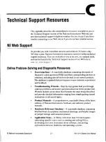
National Instruments Web support, C-1 to C-2
0
online problem-solving and diagnostic
resources, C-C-1
optional equipment, 1-3
P
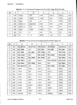
P1
(J1)
connector pin assignments
peripheral slot (table), B-5 to B-6
Star Trigger slot (table), B-3 to B-4
System Controller slot (table), B-1 to B-2
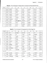
P2 (J2) connector pin assignments
peripheral slot (table), B-6
Star Trigger slot (table), B-4 to B-5
System Controller slot (table), B-2 to B-3
peripheral slots
description, 1-8
PI (J1) connector pin assignments (table),
B-5 to B-6
P2 (J2) connector pin assignments
(table), B-6
parts locator diagram, 1-4
power cables (table), 1-2
power failure, troubleshooting (table), 3-3
problem-solving and diagnostic resources,
online, C-1
PXI subsystem, 1-7 to 1-10
backplane specifications, A-4
cooling specifications, A-2 to A-3
electrical characteristics, A-1 to A-2
AC input, A-1
DC output, A-1 to A-2
installation, 2-1 to 2-2
connecting safety ground, 2-2
filler panel installation, 2-3
procedure, 2-2
interoperability with CompactPCI, 1-7
local bus, 1-8
peripheral slots, 1-8
SCXI control slot, 1-9
Star
Trigger and local bus routing
(figure), 1-9
Star Trigger slot, 1-8
System Controller slot, 1-8
system reference clock, 1-9 to 1-10
trigger bus, 1-9
PXI-1011 Chassis User Manual
1
-
2
w
w
w
.
n
i
.
c
o
i
n