


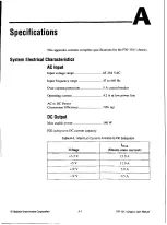


Chapter 1 Introduction
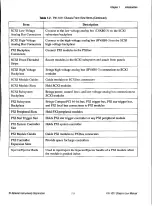
Table 1-3.
PXI-1011 Chassis Rear View Items (Continued)
Item
Description
Circuit Breaker
Protects both you and the chassis from electrical injury/damage in case
of a overcurrent fault
Power Entry Module
IEC receptacle for power input
SCXI Subsystem Overview
You can use the SCXI subsystem in the following ways:
• I n s t a l l several SCXI modules and use a DAQ device in slot 4 of the PXI
subsystem to control and/or acquire data from all the SCXI modules.
• I n s t a l l several SCXI modules and connect one of them to a
DAQ device that controls and/or acquires data from all of the
SCXI modules.
Install SCXI modules that are each dedicated to conditioning signals
for only a single DAQ device (for example, in parallel mode) or that
operate independently and only use the SCXI subsystem as a power
source and/or container. You can use the chassis this way in addition to
or instead of one of the first two methods.
The chassis address of a PXI-1011 chassis is hard-wired as 0.
PXI Subsystem Overview
The following sections describe the PXI subsystem.
Interoperability with CompactPCl
The PXI subsystem is interoperable with PXI-compatible products and
standard CompactPCl products. This is an important feature because many
PXI-compatible systems may require components that do not implement
PXI-specific features.
For example, you may want to use a standard CompactPCl network
interface card in a PXI chassis. The signals on the PXI-1011 backplane
P1 connector meet the requirements of the CompactPCl specification for
both the peripheral and system modules. The PXI-specific signals are
located on the P2 connector and are found only on the signals that are
reserved or not used in the CompactPCl 64-bit specification. Therefore, all
modules that meet the CompactPCl 64-bit specification requirements will
function in the PXI-101 1.
© National Instruments Corporation
1-7
P
X
I
-
1
0
1 1
Chassis User Manual