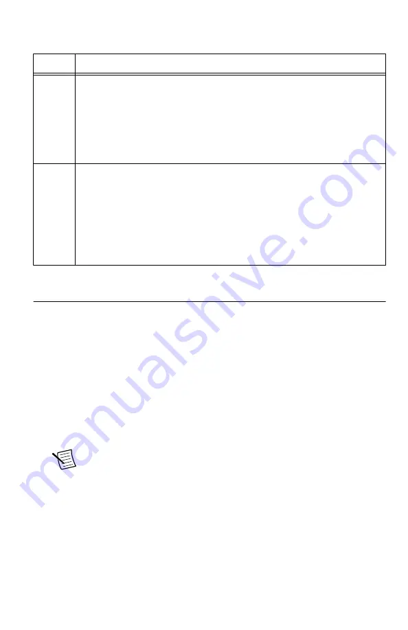
background image

Table 3.

 The NI 5624R IF Digitizer Front Panel LEDs

LED

Indication


ACCESS Indicates the basic hardware status of the NI 5624R module.

OFF—The module is not yet functional, or the module has detected a
problem with a PXI Express power rail.

AMBER—The module is being accessed. 

Accessed

 means that the device

setup registers are being written to in order to control the device.

GREEN—The module is ready to be programmed.

ACTIVE Indicates the NI 5624R module state.

OFF—User has not turned on LED.

AMBER—User defined.

GREEN—User defined.

RED—The module has detected a PLL unlock or an error state, such as a
clock fault, a power shutdown condition, or a thermal shutdown condition.
The behavior of this LED can also be user-defined.

Configuring the NI 5624R in MAX

Use Measurement & Automation Explorer (MAX) to configure your National Instruments
hardware. MAX informs other programs about which devices reside in the system and how
they are configured. MAX is automatically installed with NI LabVIEW Instrument Design
Libraries for IF Digitizers.
1.

Launch MAX.

2.

In the configuration tree, double-click 

Devices and Interfaces

 to see the list of installed

devices.

Installed devices appear under the name of their associated chassis.

3.

Expand your 

Chassis

 tree item.

MAX lists all devices installed in the chassis. Your default device names may vary.

Note


If you do not see your device listed, press <F5> to refresh the list of

installed devices. If the device is still not listed, power off the system, ensure
the device is correctly installed, and restart.

4.

Record the device identifier MAX assigns to the hardware. Use this identifier when
programming the NI 5624R.

5.

Self-test the device by selecting the device in the configuration tree and clicking 

Self-

Test

 in the MAX toolbar.

The MAX self-test performs a basic verification of hardware resources.

10

  | 

ni.com

  | 

NI PXIe-5624R Getting Started Guide

Summary of Contents for NI PXIe-5624R

Page 1: ...rs Documentation Note The NI 5624R can be used on its own or as a component of certain NI vector signal analyzers Refer to the documentation for your vector signal analyzer for information about using...

Page 2: ...ith shielded cables and accessories Caution To ensure the specified EMC performance the length of all I O cables must be no longer than 3 m 10 ft Verifying the System Requirements To use the NI 5624R...

Page 3: ...ems A PXI Express chassis and chassis documentation The NI PXIe 1085 chassis is one available option for your PXI Express device For more information about compatible chassis options visit ni com info...

Page 4: ...NI 5624R You can use the instrument design libraries to control or customize your NI 5624R device to suit the needs of your application This software offers many LabVIEW libraries to assist you in con...

Page 5: ...in the installation prompts to install the default installation Windows users may see access and security messages during installation Accept the prompts to complete the installation Note The default...

Page 6: ...ack plastic connectors from all the captive screws on the module front panel 7 Identify a supported slot in the chassis The following figure shows the symbols that indicate the slot types Figure 2 Cha...

Page 7: ...sis using the front panel mounting screws Note Tightening the top and bottom mounting screws increases mechanical stability and also electrically connects the front panel to the chassis which can impr...

Page 8: ...NI 5624R Front Panel The NI 5624R front panel contains five connectors and two LEDs Figure 4 NI 5624R IF Digitizer Module Front Panel ACCESS ACTIVE 8 ni com NI PXIe 5624R Getting Started Guide...

Page 9: ...function digital I O DIO connector for triggers or events CLK IN SMA connector Input for an external ADC Clock Sample Clock or Reference Clock to the digitizer CLK OUT SMA connector Output for an ADC...

Page 10: ...ware MAX informs other programs about which devices reside in the system and how they are configured MAX is automatically installed with NI LabVIEW Instrument Design Libraries for IF Digitizers 1 Laun...

Page 11: ...ule and select Self Calibrate on the device toolbar In LabVIEW select the Self Calibrate VI located at FPGA Interface Software Designed Instruments IF Digitizers Calibration Making a Measurement with...

Page 12: ...nel System and Maintenance Device Manager Windows XP Select Start Control Panel System Hardware Device Manager 5 If you are using a PXI controller verify that a National Instruments entry appears in t...

Page 13: ...EW 2014 FPGA Module Help Learn LabVIEW Basics NI 5624R Sample Projects Note The NI IF Digitizers Help is an HTML version of a traditional user manual that includes detailed information about device fe...

Page 14: ...rks and Logo Guidelines at ni com trademarks for information on National Instruments trademarks Other product and company names mentioned herein are trademarks or trade names of their respective compa...

Reviews: