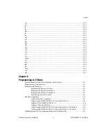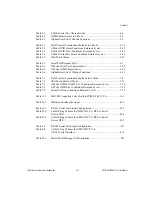
Contents
©
National Instruments Corporation
xi
Appendix E
Interfacing to an RS-485 Device
Appendix I
Programming Steps and Examples
Appendix J
Technical Support Resources
Figures
The AC Version Front Panel .................................................................1-3
The DC Version Rear Panel ..................................................................1-4
The AC Version Rear Panel ..................................................................1-5
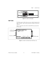
Location of the Connectors and the DC Power Jack.............................1-5
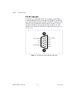
The RS-232 Connector and Signal Designations ..................................1-6
The RS-485 Connector and Signal Designations ..................................1-7
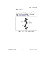
The GPIB Connector and Signal Designations .....................................1-8
Example of S Mode System Setup ........................................................2-2
Example of G Mode System Setup .......................................................2-3
Default Setting (S Mode) for DIP Switch .............................................3-4
Switch Settings to Match IBM PC Defaults..........................................3-6
Sample Switch Settings with an IBM PC or Compatible......................3-6

