Chapter 1
Hardware Overview
1-4
www.ni.com
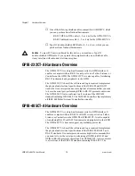
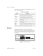
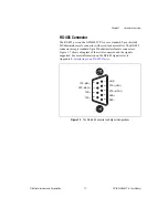
The LEDs show the current status of the GPIB-232/485CT-A at all times.
Table 1-1 describes each LED.
Rear Panel
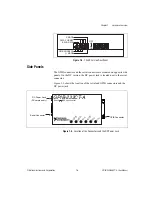
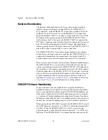
The configuration switches are located on the rear panel of the
GPIB-232/485CT-A. Figure 1-3 shows the rear panel of the AC version.
Figure 1-4 shows the rear panel of the DC version. The unmarked DIP
switches are reserved for future development and should remain in the
OFF position.
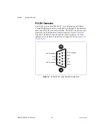
Figure 1-3.
The DC Version Rear Panel
Table 1-1.
LED Descriptions
LED
Indication
POWER
Indicates that power to the unit has been applied and
the ON/OFF switch is in the ON position.
READY
Indicates that the power-on self-test has passed
successfully and the unit is ready to operate.
TALK
Indicates that the GPIB-232/485CT-A is addressed as
a GPIB Talker.
LISTEN
Indicates that the GPIB-232/485CT-A is addressed as
a GPIB Listener.
SRQ
Indicates that the GPIB signal line SRQ* is asserted.
ATN
Indicates that the GPIB signal line ATN* is asserted.
* indicates that the signal is active low (negative logic or low when asserted).
OFF
ON
ON
OFF
S MODE
DATA FORMAT
BAUD RATE
GPIB ADDRESS
G MODE


