National Instruments FieldPoint FP-2000 User Manual Download Page 35

Chapter 3

Hardware and Software Configuration

FP-2000/2010/2015 User Manual

3-8

ni.com

3.

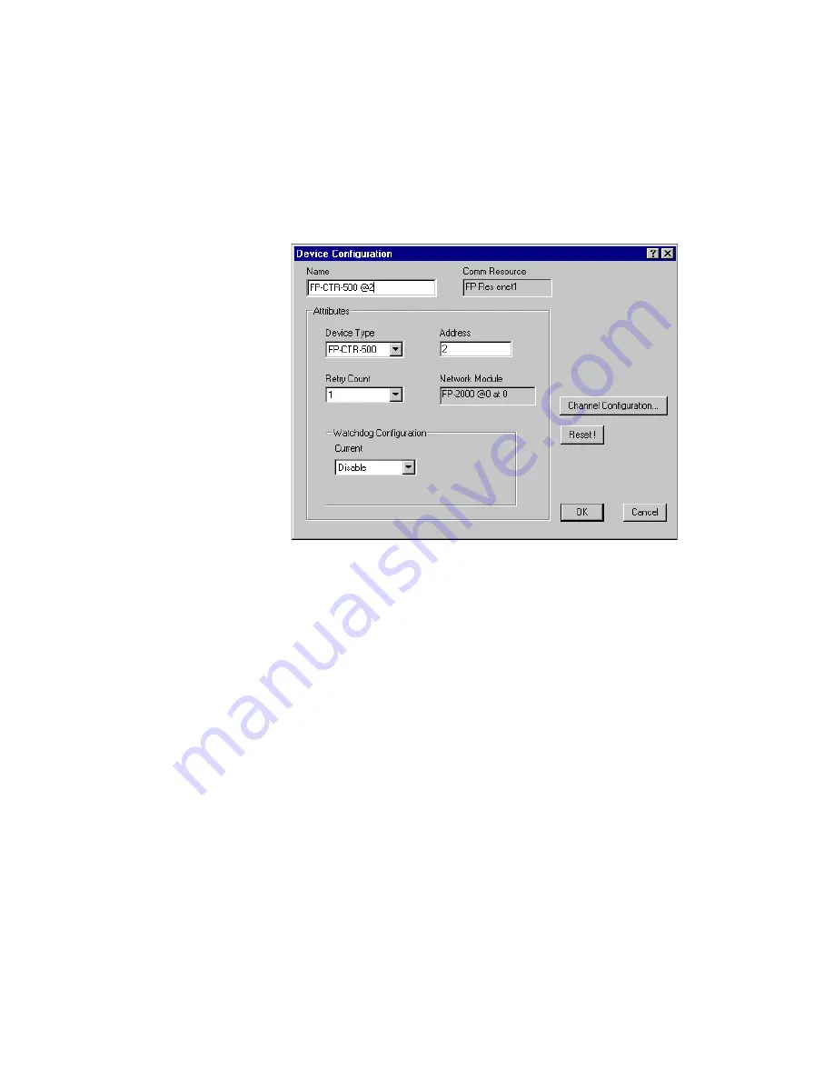
To configure the hardware settings of a particular I/O module,
right-click the device name and select

Edit this device

. The Device

Configuration dialog box appears, as shown in the following figure.

For output modules, you can choose settings for

Watchdog

Configuration

. Refer to the

Guarding against Network Failures

(Network Watchdog)

section of Chapter 4,

Feature Set Description

,

for more information about the network watchdog feature.

Summary of Contents for FieldPoint FP-2000

Page 1: ... Edition Part Number 370705A 01 Note to Users The contents of this document that refer to FieldPoint software are not intended for use with FieldPoint Software 4 0 or LabVIEW 7 0 Refer to the Measurement Automation Explorer Help for FieldPoint and the FieldPoint LabVIEW Interface Help ...

Page 2: ...24 Germany 49 0 89 741 31 30 Greece 30 2 10 42 96 427 India 91 80 51190000 Israel 972 0 3 6393737 Italy 39 02 413091 Japan 81 3 5472 2970 Korea 82 02 3451 3400 Malaysia 603 9131 0918 Mexico 001 800 010 0793 Netherlands 31 0 348 433 466 New Zealand 64 09 914 0488 Norway 47 0 32 27 73 00 Poland 48 0 22 3390 150 Portugal 351 210 311 210 Russia 7 095 238 7139 Singapore 65 6226 5886 Slovenia 386 3 425 ...

Page 3: ...r maintenance instructions owner s modification of the product owner s abuse misuse or negligent acts and power failure or surges fire flood accident actions of third parties or other events outside reasonable control Copyright Under the copyright laws this publication may not be reproduced or transmitted in any form electronic or mechanical including photocopying recording storing in an informati...

Page 4: ... names and LED names FP 20xx FP 20xx refers to the FP 2000 FP 2010 and FP 2015 italic Italic text denotes variables emphasis a cross reference or an introduction to a key concept This font also denotes text that is a placeholder for a word or value that you must supply monospace Text in this font denotes text or characters that you should enter from the keyboard sections of code programming exampl...

Page 5: ...Bases from the Panel 2 10 Mounting I O Modules onto Terminal Bases 2 10 Connecting the FP 20xx to the Network 2 11 Wiring Power to the FieldPoint System 2 13 Calculating Power for a FieldPoint Bank 2 14 Connecting to Field Devices 2 15 Powering Up the FP 20xx 2 15 Installing Software on the Host PC 2 15 Chapter 3 Hardware and Software Configuration Configuring the FP 20xx in FieldPoint Explorer 3 ...

Page 6: ...Snapshot Method 4 2 Configurable Power Up Method 4 3 Inserting Removing and Replacing I O Modules HotPnP 4 3 LED Indicators 4 4 POWER LED 4 4 STATUS LED 4 4 LINK LED 4 5 ACTIVE LED 4 5 100 Mbps LED 4 5 User Configurable LEDs A D for Count Output Channels 5 8 4 5 Power On Self Test POST 4 5 DIP Switches 4 6 DISABLE VI Switch 4 6 SAFE MODE Switch 4 7 RESET Switch 4 7 User Configurable DIP Switches 1...

Page 7: ...I Settings Tabs 5 10 Application Settings and Installer Settings Tabs 5 10 Launching Embedded Applications at Startup 5 10 File Transfer Capability 5 11 Hardware Watchdog 5 11 Appendix A Choosing Network Settings Appendix B Resetting the FP 20xx Appendix C Troubleshooting Appendix D Installing LabVIEW RT Software Appendix E Specifications Appendix F Technical Support and Professional Services Glos...

Page 8: ...LabVIEW RT engine on an FP 20xx the module can run applications without input from the host computer You can use a separate host PC running Windows to control the FP 20xx through an Ethernet connection Refer to the LabVIEW RT User Manual for more information about the LabVIEW RT engine Besides the Ethernet port the FP 20xx has an RS 232 serial port that is accessible through software It also has L...

Page 9: ...Ethernet network is limited only by your network topology The FP 20xx network module connects directly to a 10 or 100 Mbps Ethernet network The module auto detects the speed of the connection and configures itself accordingly Figure 1 2 shows an FP 20xx connected to an Ethernet network For detailed hardware specifications and cabling information refer to Appendix E Specifications 1 DIP Switches 2 ...

Page 10: ...ations and hardware details simplifying programmatic access to I O channels Version 3 0 1 of the FieldPoint software runs on Windows 2000 NT 4 0 XP Me 9x and includes the following components FieldPoint Explorer configuration utility LabVIEW VIs LabWindows CVI Functions Lookout driver Measurement Studio instrument drivers OPC Server You can download a current version of FieldPoint software from th...

Page 11: ... modules 2 Install the software as described in Chapter 2 Installing the Hardware and Software a Install programming software LabVIEW RT b Install FieldPoint Explorer 3 Configure the FieldPoint system and verify the configuration as described in Chapter 3 Hardware and Software Configuration a Configure FP 20xx network settings b Configure I O module ranges and settings c Configure security d Test ...

Page 12: ...rnet cable screwdriver FieldPoint Software CD A host PC running Windows 2000 NT 4 0 XP Me 9x LabVIEW RT software LabVIEW RT User Manual FieldPoint Safety Information The following section contains important safety information that you must follow when installing and using FieldPoint products Do not operate the FieldPoint product in a manner not specified in the user manual or operating instruction...

Page 13: ...s in most cases Occasionally however a temporary conductivity caused by condensation must be expected Pollution Degree 3 means that conductive pollution occurs or dry nonconductive pollution occurs which becomes conductive due to condensation If you need to clean a FieldPoint product use a soft nonmetallic brush The product must be completely dry and free from contaminants before you return it to ...

Page 14: ...imilar equipment Installation Category III is for measurements performed in the building installation This category is a distribution level referring to hard wired equipment that does not rely on standard building insulation Examples of Installation Category III include measurements on distribution circuits and circuit breakers Other examples of Installation Category III are wiring including cable...

Page 15: ...hods Mounting the FP 20xx on a DIN Rail The FP 20xx network module has a simple rail clip for reliable mounting onto a standard 35 mm DIN rail Follow these steps if you choose to mount the module on a DIN rail 1 Write down the serial number from the back of the FP 20xx before you mount it 2 Use a flathead screwdriver to open the DIN rail clip to the unlocked position as shown in the following figu...

Page 16: ...0 2010 2015 User Manual 4 Slide the FP 20xx to the desired position along the DIN rail After it is in position lock it to the DIN rail by pushing the rail clip to the locked position as shown in the following figure After the FP 20xx is mounted to the DIN rail connect the terminal base to it ...

Page 17: ...ectors together In most cases a single FP 20xx can support up to nine terminal bases depending on the power consumption of the I O modules Refer to the Wiring Power to the FieldPoint System section for more information about power requirements 4 Place the protective cover onto the local bus connector of the last terminal base on the bank as shown in the following figure Add the rail locks by slidi...

Page 18: ...You can order the panel mount accessory part number 777609 01 from National Instruments 1 Write down the serial number from the back of the FP 20xx before you mount it 2 Use a flathead screwdriver to open the rail clip to the unlocked position as shown in the following figure 3 Snap the panel mount accessory onto the module as shown in the following figure 4 Lock the panel mount accessory into pla...

Page 19: ...x network module Follow these steps to connect terminal bases to the network module using panel mounting Caution To avoid damaging the FP 20xx and the terminal bases make sure that power is not applied to it while you install or remove terminal bases 1 Drill pilot holes in the panel to mount the terminal bases A drilling template is provided with the network module panel mount accessory 2 Connect ...

Page 20: ...l base to the connector of the last installed base In most cases a single FP 20xx can support up to nine terminal bases depending on the power consumption of the I O modules Refer to the Wiring Power to the FieldPoint System section for more information about power requirements If all the pilot holes were correctly drilled the local bus connectors should remain firmly mated after all the bases are...

Page 21: ...l first remove the terminal bases starting with the last one then remove the network module Mounting I O Modules onto Terminal Bases Generally it does not matter where you install each I O module except in the following situations If you plan to cascade power between any I O modules using the V and C terminals those modules should be grouped together For more accurate measurements you might want t...

Page 22: ... button on top of the terminal base and pull off the module Note Some older modules may require more force to remove from the terminal base Make sure you firmly pull the module straight off the terminal base Connecting the FP 20xx to the Network Connect the FP 20xx network module to an Ethernet network using the RJ 45 Ethernet port on the module Connect the RJ 45 Ethernet port of the module to an ...

Page 23: ...k you can connect the two directly using a CAT 5 crossover cable If you need to build your own cable refer to Appendix E Specifications for more information about Ethernet cable wiring connections In order to configure the FP 20xx it must reside on the same subnet as the host PC If you want to use the FP 20xx on a subnet other than the one the host PC is on first connect and configure it on the sa...

Page 24: ...n connect an optional backup power supply to the left V and C pair The FP 20xx uses the power supply with the higher voltage level The V terminal for backup power is isolated from the other V terminals The right V and C pair provides a convenient means of connecting power to the V and C terminals of a terminal base Figure 2 2 shows this optional connection called cascading power To verify that you...

Page 25: ...oint system correctly wired to power sources Figure 2 2 FieldPoint Bank with Power Connections Calculating Power for a FieldPoint Bank The power requirements for a FieldPoint bank that uses an FP 20xx network module are calculated as follows Power 4 5 W 1 1 I O Module Consumption This is the amount of power the FP 20xx network module consumes from the power supply to power itself and the I O modul...

Page 26: ... can proceed to installing the FieldPoint software If you have already assigned an IP address to the FP 20xx the STATUS LED turns off and the A B C and D LEDs come on for about 15 seconds as LabVIEW RT starts up Once they turn off the I O module READY LEDs come on and the FP 20xx is ready for use If the STATUS LED does not light up as described here refer to the STATUS LED Error Indications sectio...

Page 27: ...ive on your computer 4 Follow the onscreen instructions to complete the installation Note If the setup does not launch automatically select Start Run from Windows enter d setup where d is the letter of your CD ROM drive and select OK The hardware and software installation is now complete Proceed to Chapter 3 Hardware and Software Configuration ...

Page 28: ...ed with FieldPoint Explorer follow these steps 1 Make sure that LabVIEW RT and the FieldPoint hardware and software have been installed as explained in Chapter 2 Installing the Hardware and Software and in the LabVIEW RT manual Verify that the FieldPoint system is powered on 2 From the Windows Start menu select Programs National Instruments FieldPoint FieldPoint Explorer to launch FieldPoint Explo...

Page 29: ... server The Comm Resource Configuration dialog box appears 4 To use the FP 20xx set the Type to Ethernet as shown in the following figure Each Ethernet comm resource represents a single bank of FieldPoint modules on the network 5 Click Browse to launch Remote System Explorer shown in the following figure ...

Page 30: ...of the System Configuration dialog box shown in the following figure Refer to Appendix A Choosing Network Settings for more information about choosing appropriate addresses for these fields You also can click Suggest Values to let the software provide default parameters If your network does not have a gateway server or DNS server you should set these parameters to 0 0 0 0 IP Address The unique com...

Page 31: ...xplorer Refer to the Giving Your FP 20xx a Host Name section of Appendix A Choosing Network Settings for more information about using this name on your network Comment To help you identify your FP 20xx Password protect Resets Determines whether the user is allowed to reset the FieldPoint bank remotely If this checkbox is selected the user must provide the password in order to reset the system remo...

Page 32: ...re on Time Server is not a required parameter after the time has been set The FP 20xx has an internal battery backed clock that provides consistent timestamps in the absence of a Time Server 10 Click OK in the System Configuration dialog box Click Yes when prompted to reboot the FP 20xx After the FP 20xx has rebooted it appears in Remote System Explorer with the updated IP address and comment as s...

Page 33: ...fter you have configured the FP 20xx in FieldPoint Explorer follow these steps to configure your FieldPoint devices and channels 1 In the Comm Resource Configuration dialog box click Find Devices to search for all of the FieldPoint devices on this communications resource If the Comm Resource Configuration dialog box is not already open right click the Comm Resource in FieldPoint Explorer and selec...

Page 34: ...etwork as shown in the following figure The hierarchy includes all of the modules connected to the FP 20xx The default name of each device found includes the name of the FieldPoint module followed by a space the sign and the address of the module for example FP 2000 0 For each module found one I O Item is created for each channel on the module and if all the channels are of the same type one I O I...

Page 35: ...lick the device name and select Edit this device The Device Configuration dialog box appears as shown in the following figure For output modules you can choose settings for Watchdog Configuration Refer to the Guarding against Network Failures Network Watchdog section of Chapter 4 Feature Set Description for more information about the network watchdog feature ...

Page 36: ... the channel s that you want to change To select more than one channel clear the One channel at a time checkbox b Set the range and output values of the selected channel s c Set the deadband for data communication over the network The deadband setting is a percentage of the full scale range Note A deadband for analog or count channels is applied to the data in determining whether the data is trans...

Page 37: ...p settings with either of the following options If you want only the range and attribute settings you configured in the Finding and Configuring Devices and Channels section to be saved as power up states click OK These settings are written to the nonvolatile memory of the network module If you want to save power up values for the range and attribute settings and also all the current output states ...

Page 38: ...k or unlock the system configuration with a password Device Location Use to change the search location for FP 20xx modules to the local subnet or to a specified IP address View Error Log Use to obtain detailed error information if you need to contact National Instruments technical support You can use the Remote System Explorer toolbar buttons or View menu to access the following features Large ico...

Page 39: ...Explorer and select Edit this comm resource The Comm Resource Configuration dialog box appears with the Network Security button enabled 2 Click Network Security The Network Security Settings dialog box appears with the current settings as shown in the following figure If your host machine does not have access to the FP 20xx the Access List is empty and dimmed 3 Make your additions or changes in th...

Page 40: ...he list You can have multiple matching entries for a given IP address In that case the first entry that matches the IP address is used starting from the bottom of the list To save the IP Access List to a file to be used for other FP 20xx modules select the Save checkbox and enter a file name 4 Once you are satisfied with the changes click OK A dialog box appears prompting you for the password Afte...

Page 41: ...is powered on and connected to the network Note To download the item names without saving the iak file right click the Comm Resource and select Download Configuration To disable a configuration download when you select File Save uncheck Options Download Configuration On Save Verifying the Configuration You can verify the installation and configuration by monitoring an I O channel or writing to an ...

Page 42: ...ing to an Output Channel You can write to output channels of I O Items that you have configured 1 In the left pane of FieldPoint Explorer select a device with output channels 2 Select the I O Item in the right pane that corresponds to the channel to which you want to write 3 Click the pencil and paper icon in the toolbar to write to the I O channel s represented by the I O Item ...

Page 43: ...tes easily with National Instruments Lookout 4 0 and later You can access the module the same way you would access another desktop computer running Lookout You can access the channel data ranges attributes and commands from Lookout as well as several control variables such as Reset and Snapshot To access the FP 20xx with Lookout 3 8 or earlier use the FieldPoint OPC server You cannot use the Field...

Page 44: ...RT Programming A simple FieldPoint application to read an I O Item might only need to use four of the VIs To create an example of such an application complete the following steps 1 Use FP Open to open the server By default the server opens with the configuration file you last saved with FieldPoint Explorer 2 Use FP Create Tag to create a handle to an I O Item that you defined in FieldPoint Explore...

Page 45: ...s an example of a LabVIEW diagram with FieldPoint items LabWindows CVI Functions and the FP 20xx When you install the FieldPoint software a LabWindows CVI instrument driver for FieldPoint is installed if LabWindows CVI has already been installed on your computer This instrument driver includes function panels to call C functions that directly access the I O Items you configured in the FieldPoint E...

Page 46: ...er OPC clients differ in the features they offer and their presentation of the OPC interface However the basic steps involved are similar for most OPC clients Follow these steps to use the FieldPoint OPC server 1 Launch your OPC client 2 Open the FieldPoint OPC server National Instruments OPCFieldPoint from the OPC client This server was registered with Windows when you installed the FieldPoint so...

Page 47: ...t OPC server supports both synchronous and asynchronous reads and writes The FieldPoint OPC server uses the GetErrorString method to return error and diagnostic messages from the FieldPoint server and hardware OPC clients that do not support this method might give you error messages like Bad non specific along with an error code Some OPC clients that do not support this GetErrorString method still...

Page 48: ... fieldpoint is a URL in which http is the protocol www ni com is the network address and support fieldpoint is the locator The FieldPoint software package installs a DataSocket URL browser in LabVIEW To launch the browser select Tools Browse Network for DataSocket URLs Enter the IP address of the FieldPoint device or computer you want to browse and click Refresh After a short pause the available D...

Page 49: ...dule Folder part of a URL provides the sub folder from which you access all data items from a specific FieldPoint I O module The I O Module Folder part of a URL has the following format machine FP n where n consists of the numeric address and name of the I O module The address of the I O module is an integer from 1 to 9 where 1 represents the I O module closest to the network module and 9 represen...

Page 50: ...ther VIs and applications can browse and read write or read write from the FP 20xx These items will also be accessible in FieldPoint Explorer and the FieldPoint OPC server Serial VIs You can use the LabVIEW Serial VIs to communicate with other serial devices through the RS 232 port on the FP 20xx For example you can use the supplied FieldPoint Optomux library to communicate with an FP 1000 connect...

Page 51: ...dog state Note National Instruments recommends leaving the network watchdog disabled when you are running embedded applications on the FP 20xx Network watchdog output values can be different than power up output values For example you may want to turn on an output value when you power up but turn it off if network communication is lost The network watchdog for the bank is disabled by default Follo...

Page 52: ... rt RT watchdog for more information about the hardware watchdog Storing a Custom Power Up Configuration Setting a Power Up State with the Snapshot Method The Snapshot feature provides a single step method for storing the current state of your FieldPoint hardware for use as the power up state of the bank Caution Using the Snapshot feature overwrites any power up values you have specified for indiv...

Page 53: ...rting Removing and Replacing I O Modules HotPnP The HotPnP feature simplifies system installation configuration and maintenance You can remove I O modules and insert I O modules into empty terminal bases even while the system is engaged in network activity You do not need to power down the bank or the system In addition you do not need to change the operation of the host computer or software in or...

Page 54: ...0xx is powered up This LED indicates that the power supply connected to the FP 20xx is acceptable and that the FP 20xx is supplying power to the I O modules STATUS LED The red STATUS LED is off in normal operation mode The FP 20xx indicates specific error conditions by flashing STATUS a specific number of times Refer to the STATUS LED Error Indications section of Table 4 1 Module Configuration Res...

Page 55: ...C and D can be sent values of 0 1 or 2 LED A should be sent only 0 or 1 LED A handles a 2 as a 1 The values sent to these LEDs manifest as 0 off 1 green and 2 red Power On Self Test POST The FP 20xx runs a power on self test POST at power up to verify its own operational status The test takes several seconds does not affect the operation of the network and does not affect any of the field wiring c...

Page 56: ...for its setting to take effect If you reboot the system with more than one of these switches ON only the left most switch is read and the others are ignored DISABLE VI Switch The position of the DISABLE VI switch determines whether any VIs run at startup You can instruct the FP 20xx network module to run a VI when it starts up but if this VI consumes all of the FP 20xx CPU for any reason it can ma...

Page 57: ...position RESET Switch The position of the RESET switch determines whether the IP settings of the FP 20xx network module are reset at startup Reset the TCP IP settings if you are moving the module from one subnet to another or if you suspect that the current TCP IP settings are bad Refer to Appendix B Resetting the FP 20xx for more information about the procedure for resetting the FP 20xx User Conf...

Page 58: ...FP 20xx power connector is a 6 pin screw terminal connector that accommodates both primary and backup power supplies The FP 20xx uses the power supply with the higher voltage level indicating which supply it is using on channel 9 A value of 0 indicates the primary supply and a value of 1 indicates the backup supply ...

Page 59: ...an the host PC the RT Development System downloads any LabVIEW RT application you subsequently run to the selected target platform Refer to Chapter 1 Introduction and to Chapter 3 Software Overview of the LabVIEW RT User Manual for more information about the RT Development System Targeting LabVIEW RT to the FP 20xx When you target LabVIEW RT to your FP 20xx you can run LabVIEW RT applications on t...

Page 60: ...g figure 4 Select your target platform from the pull down menu 5 Select RT Engine on Network to target your FP 20xx Note When targeting LabVIEW RT to an FP 20xx network module the module does not need to reside on the same subnet as the host PC 6 Enter the IP address and password you specified for the FP 20xx in Remote System Explorer If no password is specified for the FP 20xx leave the password ...

Page 61: ...int I O channels Network Options When you target LabVIEW RT to a networked FP 20xx select Tools Options to access LabVIEW options The options in the Options menu only apply to the RT Development System running on the host PC You also can set options for the RT Engine on the FP 20xx when you target LabVIEW RT to the controller With LabVIEW RT targeted to your FP 20xx select Tools Network Options to...

Page 62: ...ed If your host IP address does not match any entry or matches an entry that denies access you must provide the correct password to target the FP 20xx When you try to target the RT Engine on an FP 20xx from a host PC through the RT Development System the RT Engine compares the host PC s IP address to the entries in the RT Target Access List to determine if the host PC is permitted access You defin...

Page 63: ...bers are 130 164 with the entry 130 164 The entry matches all addresses In the RT Target Access dialog box previously shown all hosts in the site com domain can target the RT Engine with the exception of all hosts in the test site com domain Additionally the hosts a test site com b test site com and 130 164 123 123 also can target the RT Engine The host public site com does not have access even th...

Page 64: ...information 2 Select Tools Network Options 3 Select RT Target Miscellaneous from the pull down menu to see the following dialog box Use the Application Path and Launch Application at Boot up settings to automatically launch a built LabVIEW RT application when you start up the FP 20xx The LabVIEW RT Engine launches the built application specified by Application Path when you start up the FP 20xx Th...

Page 65: ...ownloaded VI Path for operations that require the VI path For example the file constant Current VI s Path normally returns the path of the VI in which the constant is used This constant may be used in a VI that reads or writes data to a file on the disk When you run this VI in the LabVIEW RT Engine on the FP 20xx Current VI s Path returns the path specified in the Downloaded VI Path option appende...

Page 66: ...or example c mybuiltapp_rtengine exe target 127 127 44 108 or c mybuiltapp_host exe target host To disconnect the host PC from the RT Engine after all applications are downloaded use quithost For example c mybuiltapp_rtengine exe target 127 127 44 108 quithost Using Application Builder When you target LabVIEW RT to your FP 20xx use the Application Builder to embed LabVIEW RT applications on your F...

Page 67: ...l VI 7 Navigate to the location of the VI to be added 8 Select the VI to be added 9 Click OK 10 Click Build Target Tab On the Target tab the Application Builder determines the Target file name Destination directory and Support file directory from the Application Path setting in Network Options You cannot change the Application name Destination directory and Support file directory settings in the A...

Page 68: ...d the file serpdrv to your application in the Source Files tab The serial port driver is installed on the FP 20xx with the RT Engine Manually adding serpdrv to your application adds the Windows driver which is not compatible with the LabVIEW RT Engine on the FP 20xx Application Settings and Installer Settings Tabs The Application Settings and Installer Settings tabs are disabled when you target La...

Page 69: ...com for more information about purchasing and using the LabVIEW Enterprise Connectivity Toolset Note Contact NI to determine whether the toolkit version you are using can be downloaded onto the FP 20xx Hardware Watchdog In addition to the network watchdog described in Chapter 4 Feature Set Description the FP 20xx network modules support the hardware watchdog available in LabVIEW RT You can use the...

Page 70: ...nts Time Service Time Service is installed along with the FieldPoint software and runs automatically Ask the network administrator to provide the proper subnet mask gateway and DNS server addresses Choosing an IP Address without a Network Administrator If you are assembling your own small Ethernet network you can choose your own IP address The following guidelines may help you choose appropriate v...

Page 71: ... have a subnet mask of 255 255 0 0 all systems with an IP of 10 10 x x are considered part of the same subnet Using the Suggest Values button when configuring a network module s IP address in FieldPoint Explorer should result in values that work on your network The Time Server is the address of the computer where you have installed the National Instruments Time Service This service is installed al...

Page 72: ...the hosts files on each networked computer A hosts file allows a networked computer to use host names when no DNS server is available Each computer on the network that needs to access the FP 20xx should have a properly configured hosts file Setting up a Hosts File Under Windows 2000 NT XP 1 Log on as an administrator to the local machine not onto a domain 2 Create a text file called hosts This fil...

Page 73: ...e TCP IP settings 1 In FieldPoint Explorer right click the Comm Resource and select Edit this comm resource 2 Click Browse to launch Remote System Explorer 3 In Remote System Explorer double click the serial number of the FP 20xx whose settings you would like to view or change 4 When you are done click OK Click Cancel to discard any changes you have made ...

Page 74: ...iguration is preserved Send a Reset command in FieldPoint Explorer to reset an individual I O module The device appears as Unconfigured in Remote System Explorer The system is unlocked and any password protection is removed for configuration settings data points and LabVIEW remote access Resetting does not affect power up defaults watchdog settings or VIs Follow these instructions to reset the uni...

Page 75: ...communicate over Ethernet to the FP 20xx Select Start Settings Control Panel and double click Network TCP IP should appear in the list of installed network components If it does not appear select Protocol from the Network Component Type dialog box and click Add In the Select Network Protocol dialog box that appears select Microsoft as the manufacturer and TCP IP from the Network protocol list Clic...

Page 76: ... moved to the current network Refer to Appendix B Resetting the FP 20xx for instructions on resetting the FP 20xx You may be using the wrong type of Ethernet cable You may have assigned an IP address to your FP 20xx that is already used by another device on the network Either remove or reconfigure the other device or reconfigure the FP 20xx IP address Refer to Appendix A Choosing Network Settings ...

Page 77: ...on installing the FieldPoint software which includes Time Services No Modules Found Error in FieldPoint Explorer Possible causes and solutions Make sure that the FieldPoint hardware is powered on Make sure terminal bases are firmly mated I O modules are firmly seated on the terminal bases and the cable connections are secure The I O module READY LEDs should be lit if all these connections are good...

Page 78: ...TUS LED a specific number of times The following table describes the STATUS LED flashing sequences and the corresponding error condition Table C 1 STATUS LED Flashes and Corresponding Error Conditions Number of Flashes Error Condition 0 stays lit The FP 20xx did not power on correctly Contact National Instruments for assistance 1 The FP 20xx is in reset mode or is unconfigured Refer to Appendix B ...

Page 79: ...e and version numbers as shown in the following figure Installing or Upgrading LabVIEW RT on the FP 20xx Your FP 20xx has LabVIEW RT pre installed However if the FP 20xx STATUS LED flashes three times and its status in Remote System Explorer is No software installed the FP 20xx is in safe mode In this case you should re install or upgrade the LabVIEW RT software Complete the following steps to ins...

Page 80: ...og box appears asking if you want to delete Click OK 6 Click Proceed 7 When installation is complete click Close to exit the Install Upgrade Software dialog box Click Yes when prompted to reboot the system 8 After the FP 20xx has rebooted select View Refresh to view the system configuration The status should now be Running Once you assign the IP address and install the LabVIEW RT software the FP 2...

Page 81: ... Mbps 100 Mbps auto negotiated Maximum cabling distance 100 m segment Maximum power to connected terminal bases 9 W Maximum number of banks Determined by network topology Memory FP 2000 16 MB nonvolatile 16 MB DRAM FP 2010 32 MB nonvolatile 32 MB DRAM FP 2015 512 MB nonvolatile 32 MB DRAM Power Requirement Power supply range 11 to 30 VDC Power consumption 4 5 W 1 1 I O Module Consumption ...

Page 82: ...tion Degree 2 Safety The FP 20xx meets the requirements of the following standards for safety and electrical equipment for measurement control and laboratory use EN 61010 1 1993 A2 1995 IEC 61010 1 1990 A2 1995 UL 3101 1 1993 UL 3111 1 1994 UL 3121 1998 CAN CSA c22 2 no 1010 1 1992 A2 1997 Electromagnetic Compatibility CE C Tick and FCC Part 15 Class A Compliant Electrical emissions EN 55011 Class...

Page 83: ...ing connections for both normal and crossover cables The following figure shows the connector pinouts for FieldPoint Ethernet cables Table E 1 Ethernet Cable Wiring Connections Pin Connector 1 Connector 2 Normal Connector 2 Crossover 1 white orange white orange white green 2 orange orange green 3 white green white green white orange 4 blue blue blue 5 white blue white blue white blue 6 green green...

Page 84: ... measurement glossary and so on Assisted Support Options Contact NI engineers and other measurement and automation professionals by visiting ni com support Our online system helps you define your question and connects you to the experts by phone discussion forum or email Training Visit ni com custed for self paced tutorials videos and interactive CDs You can also register for instructor led hands ...

Page 85: ... certificate for your product at ni com calibration If you searched ni com and could not find the answers you need contact your local office or NI corporate headquarters Phone numbers for our worldwide offices are listed at the front of this manual You also can visit the Worldwide Offices section of ni com niglobal to access the branch office Web sites which provide up to date contact information ...

Page 86: ...Bytes bank The combination of one FieldPoint network module and one or more terminal bases and I O modules C Celsius DIP switch Dual Inline Package switch DNS Domain Name System FTP File Transfer Protocol HotPnP Hot Plug and Play I O Input Output IEC International Electrotechnical Commission LED Light emitting diode m Meters OPC OLE for Process Control PG Pulse Generation POST Power On Self Test ...

Page 87: ...other Data will not flow through an intermediate router TCP Transmission Control Protocol A set of standard protocols for communicating across a single network or interconnected set of networks TCP is for high reliability transmissions UDP User Datagram Protocol A set of standard protocols for communicating across a single network or interconnected set of networks UDP is for low overhead transmiss...

Page 88: ...iting to an output 3 15 cleaning your FP 20xx 2 2 Comm Resource configuration 3 2 3 12 troubleshooting browse errors C 1 configuration channel configuration 3 9 Comm Resource configuration 3 2 3 12 C 1 connecting to field devices 2 15 custom power up configuration 4 2 devices and channels 3 6 HotPnP Hot Plug and Play 4 3 overview 1 4 saving hardware configuration as power up state 3 10 saving syst...

Page 89: ...1 cabling connections table E 3 connecting FP 20xx to network 2 11 connections ACTIVE LED indicator 4 5 figure 1 3 LINK LED indicator 4 5 methods 2 12 example code F 1 F factory configuration 3 10 FieldPoint bank definition 1 2 FieldPoint Explorer configuring devices and channels 3 6 configuring the FP 20xx 3 1 downloading configuration to FP 20xx 3 14 installation 2 15 monitoring I O channels 3 1...

Page 90: ...ew 1 4 snapshot feature 4 2 specifications E 1 targeting LabVIEW RT to the FP 20xx 5 1 TCP IP settings A 4 transferring files to and from FP 20xx 5 11 using with host PC software DataSocket communication 3 20 LabVIEW 3 17 LabVIEW Publish Data VI 3 23 LabVIEW serial VIs 3 23 LabVIEW TCP and UDP VIs 3 23 LabWindows CVI 3 18 Lookout 3 16 OPC server 3 19 overview 3 16 FTP National Instruments FTP site...

Page 91: ...terminal bases 2 10 overview 1 4 power connections 2 13 2 14 figure 2 14 removing I O modules 2 11 Installer Settings tab in Application Builder 5 10 instrument drivers F 1 IP Access List 3 12 3 13 IP address See also gateway IP address DNS address time server subnet mask choosing A 1 configuring 3 3 error when configuring C 2 resetting with Reset switch 4 7 B 1 IP Pattern 3 13 isolation defeated ...

Page 92: ...F 1 professional services F 1 system integration services F 1 technical support F 1 worldwide offices F 2 network module See FP 20xx hardware network security settings 3 12 network specifications E 1 network watchdog 4 1 network See Ethernet network O online technical support F 1 OPC client 3 19 3 20 OPC server 3 19 3 20 overview FieldPoint software 1 3 FP 20xx hardware 1 1 setup 1 4 using FP 20xx...

Page 93: ...g unlocking Remote System Explorer settings 3 13 network security settings 3 12 password protected resets 3 4 serial data communication 3 23 serial port 1 1 3 23 4 7 serial VIs 4 7 snapshot feature 3 10 4 2 software drivers F 1 specifications cabling E 3 electromagnetic compatibility E 2 environmental E 2 memory E 1 network E 1 physical characteristics E 2 power requirements E 1 safety E 2 STATUS ...

Page 94: ...timestamp values C 2 IP configuration errors C 2 No Modules Found error C 3 No Software Installed status C 3 Remote System Explorer browse errors C 1 runaway startup applications C 4 STATUS LED error indications table C 4 troubleshooting resources F 1 U UDP data communication 3 23 upgrading software on the FP 20xx D 1 V VIs See LabVIEW VIs W watchdog 4 1 5 11 Web professional services F 1 technica...

Reviews: