background image

5

GAS HOOK-UP INSTRUCTIONS

CYLINDER CONNECTION:


Ensure that the gas regulator hose is kink free. Remove the cap or plug from the cylinder fuel

valve. Insert the black QCC1 regulator nipple onto the QCC1 fuel valve. Hand tighten clockwise. 

Do not use tools. Leak test all

joints prior to using the barbecue. 

A leak test must be performed annually, and each time a cylinder is hooked up, or if a part

of the gas system is replaced.

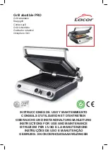
PROPANE CYLINDER INSTALLATION

:


Set cylinder into the groove of the lower tank mounting bracket. Ensure that

tank valve faces away from the barbecue. Lower the top tank mounting bracket onto the cylinder and tighten with wing nut.

IMPORTANT: Ensure that the hose is routed around the front side of the cart leg to maintain  proper clearance to
the underside of the unit.

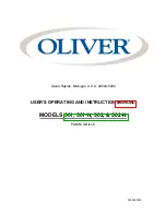
NATURAL GAS HOOK-UP:


This natural gas grill is supplied with a 10ft supply hose (complete with a quick disconnect)

designed for natural gas and certified for outdoor use.  The gas grill is designed to operate at an inlet pressure of 7 inches water
column.   A regulator must be installed if the house pressure is greater than 7 inches water column.   Piping and valves upstream
of the quick disconnect are not supplied.
The quick disconnect must not be installed in an upward direction and a readily accessible manual shut-off valve must be installed
upstream of, and as close to, the quick disconnect as is feasible.  The flared end of the hose  must be connected to the unit as
illustrated in the 

Natural Gas Hose Attachment

 diagram.  These connections must be made by a licensed gas installer.  Leak test

all joints prior to using the gas grill.

IMPORTANT: Ensure that the hose is routed around the front side of the cart leg to maintain  proper clearance to
the underside of the unit.

NON-SIDE BURNER UNITS:


Connect the flared end of the hose to the fitting on the end of the manifold tube. Wrench

tighten. (

Do not use thread sealer/pipe dope.)

SIDE BURNER UNITS:


Connect the 20" hose from the manifold, to the side burner as illustrated in the 

Natural Gas Hose

Attachment

 diagram.  Connect the supply hose to the flare connection which faces down from the side burner.  Tighten all

connections using two wrenches. (

Do not use thread sealer/pipe dope.)

LEAK TESTING INSTRUCTIONS

WARNING


The installation must be performed by a licensed gas fitter, and all connections must be leak tested before operating the grill.

• Do not route hose underneath drip pan.

• Do not route hose between space in bottom shelf and back panel.

• Do not route hose over top of rear panel.

• Ensure all  hose connections are tightened using two wrenches.  Do not use teflon tape or pipe dope on any hose connection.

• Ensure the hose does not contact any high temperature surfaces, or it may melt and leak causing a fire.

• Leak test all the connections using a soap and water solution, as per the leak testing instructions found in this manual.
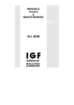
LEAK TESTING: 

 This must be done before initial use, annually and whenever any gas components are replaced or serviced. Do

not smoke while performing this test, and remove all sources of ignition.  See 

Leak Testing Diagram

 for areas to check.

1. Turn all burner controls to off. Turn supply valve on.

2. Brush a half and half solution of liquid soap and water onto all joints and connections of the regulator, hose, manifolds and

valves.

3. Bubbles will indicate a gas leak. Either tighten the loose joint or have the part replaced with one recommended by the customer

care department.

4. If the leak cannot be stopped, shut off the gas supply, disconnect it and have the barbecue inspected by your gas supplier or

dealer. Do not use the appliance until the leak has been corrected.

5. Turn off gas supply.

Do  not use an open flame to check for gas leaks.  Be sure there are no sparks or open flames in the area while you check for

leaks.  Sparks or open flames will result in a fire or explosion, damage to property, serious bodily injury or death.

DANGER

Summary of Contents for Ultra Chef UP405 PEDESTAL

Page 1: ...O CANADA L4N 4Y8 PHONE 705 726 4278 FAX 705 725 2564 EMAIL care nac on ca WEB SITE www napoleongrills com RETAIN THIS MANUAL FOR FUTURE REFERENCE GARDER CE LIVRE POUR R F RENCES FUTURES APPLY SERIAL N...

Page 2: ...e propane cylinder and the gas grill must be disconnected and the cylinder removed and stored out doors in a well ventilated space out of reach of children Disconnected cylinders must not be stored in...

Page 3: ...OLEON will not be responsible for the installation labour or any other costs or expenses related to the re installation of a warranted part and such expenses are not covered by this warranty Notwithst...

Page 4: ...ce of local codes with the current CSAC22 1 Canadian electrical code in Canada or the National Electrical Code ANSI NFPA70 in the United States Use only the pressure regulator and hose assembly provid...

Page 5: ...e manifold tube Wrench tighten Do not use thread sealer pipe dope SIDE BURNER UNITS Connect the 20 hose from the manifold to the side burner as illustrated in the Natural Gas Hose Attachment diagram C...

Page 6: ...rn burner control off Wait 5 minutes Ensuring burner controls are in the off postion turn on the gas supply valve REAR BURNER LEFT BURNER IGNITER Push igniter several times or light by match If igniti...

Page 7: ...tact with hot surfaces Clean grill in an area where cleaning solutions will not harm decks lawns or patios Do not use oven cleaner to clean any part of this gas grill Do not use a self cleaning oven t...

Page 8: ...s Re install the burner Check that the valve enters the burner when installing Replace burner cover and mounting screws to complete installation ALUMINUM CASTINGS Clean castings periodically with warm...

Page 9: ...om burner accompanied by the smell of gas and possibly difficulties in lighting Lifting flames on burner Close air shutter slightly see previous problem Paint appears to be peeling inside lid or hood...

Page 10: ...nbonne et le gril doivent tre entrepos s l ext rieur dans un endroit bien a r N installez pas le gril dans un endroit venteux Les vents forts nuiront la performance de cuisson de votre gril Lorsque le...

Page 11: ...sera pas responsable de l installation main d oeuvre ou autres co ts ou d penses relatives la r installation d une pi ce garantie car de telles d penses ne sont pas couvertes par cette garantie Nonob...

Page 12: ...collet pour prot ger la soupape de la bonbonne La bonbonne doit tre munie d un dispositif de d tection de trop plein PROPOSITION 65 DE LA CALIFORNIE La combustion de gaz cr e des sous produits parmi l...

Page 13: ...20 partir du collecteur travers la bague de fixation au dessous de la base au c t du br leur comme montr Installez le coude de 90o faisant face l arri re de l unit Raccordez le tuyau d alimentation ce...

Page 14: ...osition d arr t et ouvrir le robinet d alimentation en gaz BR LEUR DE DROITE BR LEUR ARRI RE ALLUMEUR TROU D ALLUMAGE Appuyer sur l allumeur plusieurs reprises ou allumer l aide d une allumette Si l a...

Page 15: ...vous que les br leurs sont teints avant de nettoyer viter tout contact avec les surfaces chaudes Nettoyez votre gril dans un endroit o les produits de nettoyage n endommageront pas votre patio terrain...

Page 16: ...e gril Faites remplacer la pi ce par votre d taillant ULTRACHEF ou par un installateur qualifi BR LEUR Le br leur est fait d acier inoxydable 304 mais en raison de la chaleur extr me et d un environne...

Page 17: ...ement Ne tapissez pas le tiroir d gouttement avec du papier d aluminium Consultez les instructions de nettoyage Les flammes produites par les br leurs sont jaunes et vous d tectez une odeur de gaz Pos...

Page 18: ...18 CART MODEL ONLY Mod le sur chariot seulement 8 X N570 0027 14 X 2 3 8 CART MODEL ONLY Mod le sur chariot seulement...

Page 19: ...1 4 20 x 1 2 PROPANE ONLY PROPANE SEULEMENT 3 8 3 8 TWO PEOPLE ARE REQUIRED FOR THIS STEP DEUX PERSONNNES SON N CESSAIRES POUR CETTE TAPPE CART MODEL ONLY Mod le sur chariot seulement CART MODEL ONLY...

Page 20: ...20 PEDESTAL MODEL ONLY Mod le sur socle SEULEMENT PROPANE ONLY PROPANE SEULEMENT 7 1 6 PEDESTAL MODEL ONLY Mod le sur socle SEULEMENT 3 8 4 X N570 0026 14 x 1 2...

Page 21: ...21 4 X N570 0026 14 x 1 2 3 8 PEDESTAL MODEL ONLY Mod le sur socle SEULEMENT PEDESTAL MODEL ONLY Mod le sur socle SEULEMENT...

Page 22: ...0026 14 x 1 2 PROPANE ONLY PROPANE SEULEMENT 3 8 PEDESTAL MODEL ONLY Mod le sur socle SEULEMENT TWO PEOPLE ARE REQUIRED FOR THIS STEP DEUX PERSONNNES SON N CESSAIRES POUR CETTE TAPPE 3 8 PEDESTAL MOD...

Page 23: ...1 PUSH BRACKETS TO END OF SLOTS ENFONCEZ LES SUPPORTS JUSQU AU FOND DES FENTES 2 X N570 0026 14 x 1 2 OPTIONAL LOCKING SCREW VIS DE VERROUILLAGE OPTIONNELLE 2 X N570 0029 1 4 20 x 3 8 CART MODEL ONLY...

Page 24: ...Y Mod le sur socle SEULEMENT 2 X N570 0026 14 x 1 2 OPTIONAL LOCKING SCREW VIS DE VERROUILLAGE OPTIONNELLE 5 X N570 0076 8 X 1 2 3 8 PEDESTAL MODEL ONLY Mod le sur socle SEULEMENT LOCKING OPTIONAL VER...

Page 25: ...25 2 X N305 0041 CART MODEL 2 X N305 0044 2 X N450 0005 10 24 3 8 PEDESTAL MODEL 2 X N305 0065...

Page 26: ...26 N160 0010 N185 0001 N520 0011K...

Page 27: ...gas fitter and all connections must be leak tested before operating the grill L installation doit tre effectu e par un installateur certifi pour le gaz et tous les raccordements doivent tre test s pou...

Page 28: ...neau avant PROPANE ONLY IMPROPER HOSE CONNECTION PROPANE SEULEMENT BRANCHEMENT INAD QUAT DU BOYAU Ensure the hose does not contact any high temperature surfaces or it may melt and leak causing a fire...

Page 29: ...n de garder Ensure the hose does not contact any high temperature surfaces or it may melt and leak causing a fire Assurez vous que le boyau ne touche aucune surface haute temp rature sinon il risque d...

Page 30: ...indicate a gas leak Either tighten the loose joint or have the part replaced with one recommended by the customer care department 4 If the leak cannot be stopped shut off the gas supply disconnect it...

Page 31: ...31 NOTES...

Page 32: ...end cap right embout en luxidio de le tablette lat ral gauche x 23 n570 0008 8 x 1 2 screw 8 x 1 2 vis x x x 24 n080 0019p top tank support support sup rieur de la bonbonne p p n570 0065 thumbscrew 1...

Page 33: ...helf bracket right support de la tablette lat rale droite x x 54 n080 0112p side shelf bracket left support de la tablette lat rale gauche x x 55 n030 0001p tow el bar support du crochet x x 56 n570 0...

Page 34: ...34...

Page 35: ...______________________________________________________________________________ TEL _________________________________ FAX ______________________________ EMAIL __________________________________________...

Page 36: ...36...

Reviews: