11
WS-415-55 / 11.10.97
REPLACEMENT P
REPLACEMENT P
REPLACEMENT P
REPLACEMENT P
REPLACEMENT PAR
AR
AR
AR
ARTS, GS 3500
TS, GS 3500
TS, GS 3500
TS, GS 3500
TS, GS 3500
PPPPPAR
AR
AR
AR
ART #
T #
T #
T #
T #
GA-GI-135.07
GA-GI-135.17
GA-GI-135.06
GA-GI-135.15
GA-GI-135.09
GA-GI-135.16
GL-611
GL-610
WS-385-33
WS-300-22
WS-300-21
GA-GDS-562.014
GA-GDS-562.015
GA-GS-010.441
GA-GS-010.442
GA-GDS-280.20
GA-GDS-280.21
GS-325PB
EP-230K
GA-GI-550.01
EP-715.73
DESCRIPTION
DESCRIPTION
DESCRIPTION
DESCRIPTION
DESCRIPTION
BURNER ASSEMBLY
S.I.T. VALVE - NG
S.I.T. VALVE - LP
PIEZO IGNITOR
PILOT ASSEMBLY - NG
PILOT ASSEMBLY - LP
#51 PILOT ORIFICE - NG
#30 PILOT ORIFICE - LP
BURNER ORIFICE - #36 NG
BURNER ORIFICE - #54 LP
BURNER ORIFICE - #37 HI ALT NG
BURNER ORIFICE - #55 HI ALT LP
SPILL SWITCH - NG
SPILL SWITCH - LP
THERMOCOUPLE
THERMOPILE
FLAME ADJUSTMENT KNOB EXTENSION
PILOT ON/OFF KNOB EXTENSION
BURNER ON/OFF SWITCH
CANOPY LOUVRE SET - POLISHED BRASS
PPPPPAR
AR
AR
AR
ART #
T #
T #
T #
T #
GA-GS-010.399
WS-725-25
WS-725-26
WS-357-01
WS-100-38
WS-100-39
WS-455-23
WS-455-24
WS-455-04
WS-455-03
WS-455-13
WS-455-02
WS-660-07
WS-660-06
WS-680-05
WS-680-04
WS-380-006
WS-380-007
WS-660-09
CL29PB
DESCRIPTION
DESCRIPTION
DESCRIPTION
DESCRIPTION
DESCRIPTION
BACK LOG
FRONT LOG (
PROPANE
GAS
ONLY
)
FRONT LOG (
NATURAL
GAS
ONLY
)
RIGHT LOG
CENTER LOG
LEFT LOG
LOG SET ASSEMBLYc/w CHARCOAL EMBERS
PROPANE
GAS
ONLY
LOG SET ASSEMBLYc/wCHARCOAL EMBERS
NATURAL
GAS
ONLY
NAPOLEON LOGO
FRONT DOOR GLASS
SIDE WINDOW GLASS
FRONT GLASS GASKET
SIDE GLASS GASKET
FRONT GLASS & GASKET
SIDE GLASS & GASKET
FRONT DOOR FRAME
SIDE GLASS FRAME
POLISHED BRASS FACIA
BLACK TRIVET
CHARCOAL EMBERS
ASH FENDER TRIM
C
/
W
CORNER
BRACKET
ADJUSTMENTS
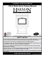
PILOT BURNER ADJUSTMENT
PILOT BURNER ADJUSTMENT
PILOT BURNER ADJUSTMENT
PILOT BURNER ADJUSTMENT
PILOT BURNER ADJUSTMENT
Adjust the pilot screw to provide properly sized flame. Turn
in a clockwise direction to reduce the gas flow.
FIGURE 17 & 18.
VENTURI ADJUSTMENT
VENTURI ADJUSTMENT
VENTURI ADJUSTMENT
VENTURI ADJUSTMENT
VENTURI ADJUSTMENT
To access the venturi, remove the four screws securing the burner to the base;
slide to the left, lift up and out. Natural gas models have air shutters set at 1/16
(.063) inch open. Propane gas models have air shutters set at 5/16 (.313) inch
open. Closing the air shutter will cause a more yellow flame, but can lead to
carboning. Opening the air shutter will cause a more blue flame, but can cause
flame lifting from the the burner ports. The flame may not appear yellow immedi-
ately; allow 15 to 30 minutes for the final flame colour to be established.
Air shutter adjustment must only be done by a qualified gas installer!
REPLACEMENTS
ORDERING REPLACEMENT P
ORDERING REPLACEMENT P
ORDERING REPLACEMENT P
ORDERING REPLACEMENT P
ORDERING REPLACEMENT PAR
AR
AR
AR
ARTS
TS
TS
TS
TS
Contact your dealer or the factory for questions concerning prices and policies on replacement parts. Normally all parts can
be ordered through your Napoleon dealer or distributor. When ordering replacement parts always give the following informa-
tion: 1. M
ODEL
& S
ERIAL
N
UMBER
OF
FIREPLACE
3. P
ART
N
UMBER
5. F
INISH
2. I
NSTALLATION
DATE
OF
FIREPLACE
4. D
ESCRIPTION
OF
PART
P
I
PI
PILOT SCREW
LOT
N
O
L
O
T
H I
LO
FF
O
FLAME MUST ENVELOP
UPPER 3/8" TO 1/2" OF
THERMOCOUPLE &
THERMOPILE
THERMO-
COUPLE
THERMOPILE
FIGURE 17
FIGURE 18
FIGURE 19