EN
W415-1789 / C / 01.29.19
29
electrical information
9.3
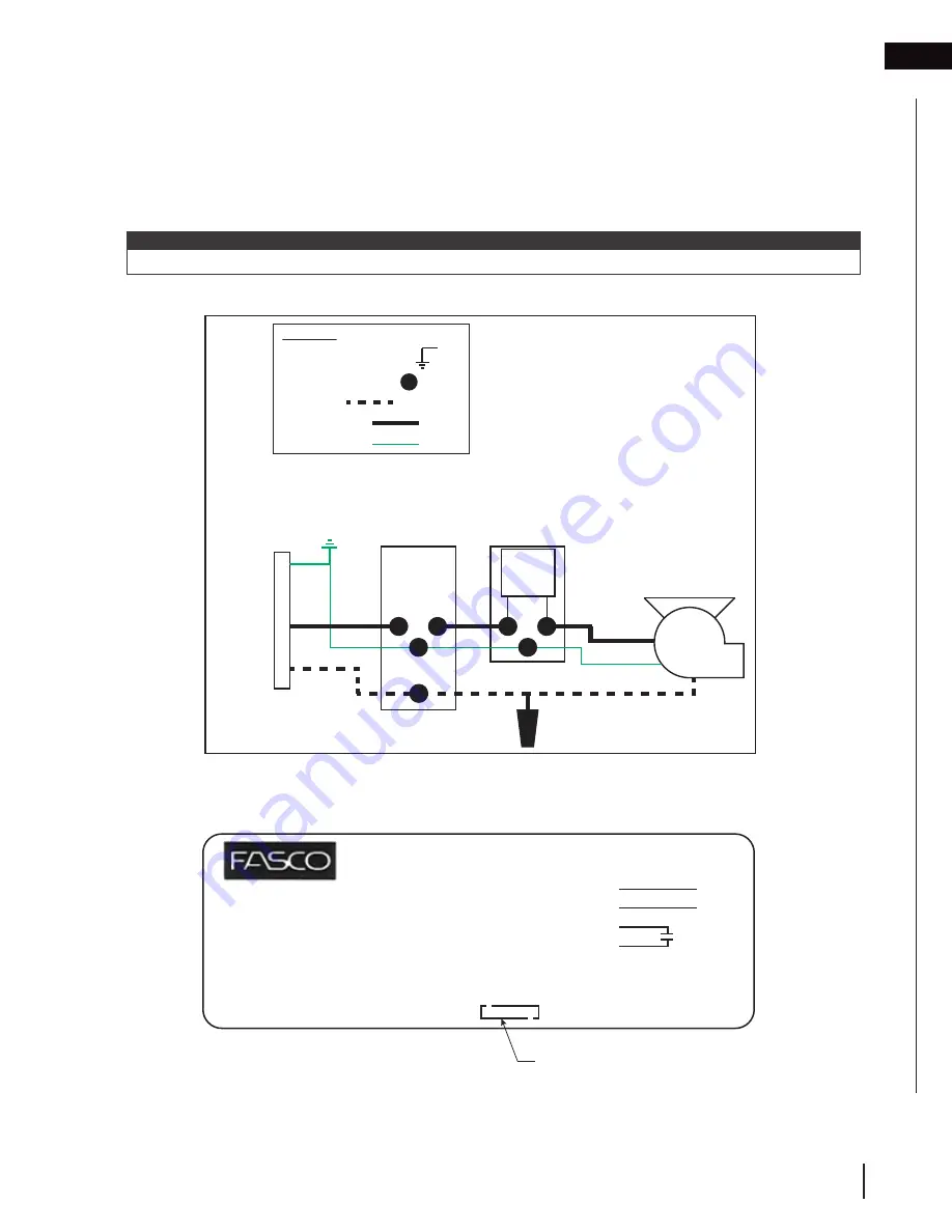
wiring to wall switch only
9.3.1 wiring diagram
On/Off Switch
in Blower
Housing
Blower
Gr
ound Connection =
Legend:
Field Connection =
On/Off
Switch
L
N
Wall
Switch
G
120VAC
14/2
Power
Source
Neutral =
L1 (120VAC) =
Ground Wire =
1. Turn off the power by locating your housebreaker, and shutting the power off to the room you will be working
in.
2. Determine the location for the wall switch (not supplied). Install an electrical box (not supplied) at the location.
3. Ensure the wires for the wall are properly wired to the switch box and are ready.
4. Connect the hot wire from the on/off switch to the wall switch.
5. Connect the neutral wires to each other from the blower to the power source neutral (N).
6. Connect the all ground from the power source to the blower.
note:
Check the blower specifications (see “blower specifications” section) before choosing a suitable wire size.
9.4
blower specifications
Assembled in Mexico
115 V
50/50Hz
Class B
0.9A/1.1A
1600 RPM
Cust P/N
Sealed Ball Brg
Thermally Protected
No.
70903602
TYPE 90B1
Connection Diagram
Wht
Line
Blk
Line
Blu
Blu
4 MFD/370 VAC
AO
61299553
00464504
00469142


