background image


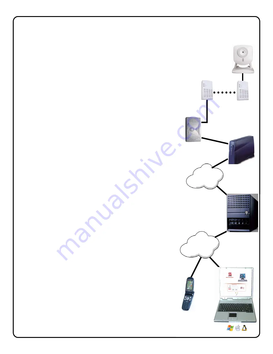
Overview of the iSeeVideo VideoAlert.net System  

Internet 

Internet 

G-BOX


VideoAlert.net  

Server  

Customer's 

Broadband  

Modem 

ISEE-VCAM1 

ISEE-EOP-MOD200 

T

he 

NAPCO iSeeVideo VideoAlert.net 

system allows remote video internet 

monitoring of residential and light commercial properties. Its unique 
subscription-based account system provides the opportunity to realize 
recurring revenue from typical CCTV video installations, The system is 
comprised of the following four components: 

The 

ISEE-VCAM1 

is a high quality IP video camera that provides video 

images with a maximum of 640 x 480 lines of resolution that can be viewed 
through the VideoAlert.net server on virtually any computer in the world at up 
to 25 fps.  The 

ISEE-VCAM1 

provides pixel based motion detection that, 

when activated, will prompt the transmission of video clips to the 
VideoAlert.net server.  The 

ISEE-VCAM1 

 provides (at no additional service 

charge) d

ynamic IP support through a DNS server - every time the broadband 

modem's IP address changes, it checks in with its DNS server to insure that 
the DHCP IP address is always kept current. 

The 

ISEE-EOP-MOD200 

is an Ethernet-Over-Power module that allows the 

transmission of video signals over the existing power lines of a home or 
business.  The simple Plug-n-Play installation allows the

 ISEE-VCAM1 

to 

communicate with the 

G-BOX

 interface module by simply connecting the 

devices to their respective EOP modules and then into the electrical outlets. 
The  modules create a 

powerline network 

ideal for the transmission of video 

signals at up to 200 megabits per second. The EOP modules are fully capable 
of transmitting data across the phases of typical residential multiphase power 
systems.     
 
The 

G-BOX 

(Patents Pending) is an Internet Video accessory that allows the 

"Plug & Play" installation of the 

ISEE-VCAM1 

camera system. Many other 

devices that allow direct connection to the internet require re-configuration of 
the router, but not the G-BOX. The G-BOX segments the network, 

automatically detects 

and properly forwards the data intended for the 

ISEE-

VCAM1 

or to the customer's computer/router, as required.  The G-BOX is 

designed to be placed between the broadband modem and router, and also 
functions as a router for cases where the customer's PC is the only device 
connected to the broadband modem.  The G-BOX provides 4 auto-sensing 
LAN ports for connection to the 

ISEE-VCAM1 

through the

 ISEE-EOP-

MOD200 

and to the customer's PC, router or other equipment. This 

revolutionary new device totally eliminates the need for TCP/IP and network 
trained professionals for typical 

ISEE-VCAM1 

installations, now allowing 

standard alarm personnel to quickly and easily install these IP devices.  The 
G-BOX functions as both a DHCP client and server, to fit seamlessly into all 
typical DHCP environments.  


The NAPCO 

VideoAlert.net 

server maintains VideoAlert accounts and allows 

subscribers to view their 

ISEE-VCAM1 

camera from any personal computer 

or web enabled cell phone.  It is compatible with computers running the 
Microsoft Windows

®

, Apple

®

 and Linux

®

 operating systems and is also 

compatible with any WAP enabled cell phone or mobile video device.  The 
server also automatically notifies the subscriber by email upon receipt of 
triggered video events and archives them for viewing at a later time.  Each 
subscriber account provides 50Mb of storage, allowing the 

archiving 

of about 

(75) 10 second video clips (adjustable 5 sec pre-alarm and 5 sec post-alarm).  
The server is designed to allow the customer to have complete control of their 
account in regard to passwords, email addresses and other personal 
information.  

Summary of Contents for iSeeVideo ISEE-VCAM1

Page 1: ...1 For Sales and Repairs 800 645 9445 For Technical Service 800 645 9440 Publicly traded on NASDAQ Symbol NSSC NAPCO 2008 Designed exclusively for use with NAPCO iSeeVideo VideoAlert net Server COMPATIBLE R G BOX IP Plug Play Module Internet VideoAlert net SERVER ISEE VCAM1 ISEE EOP MOD200 ISEE EOP MOD200 ...

Page 2: ...5 x 1 4 Weight 131g 0 29lb without stand 256g 0 56lb with stand Certification CE FCC ISEE EOP MOD200 Features Data Rate Up to 200Mbps Port Ethernet 10Base T 100Base TX LED s Power Powerline Ethernet Cabling Type Cat5 RJ 45 Security Feature AES Encryption Security Key Bits 128 Power One AC Plug 100 240V 50 60 Hz Standards HomePlug AV Standard IEEE 802 3 IEEE 802 3u Compliances IEEE 802 3 IEEE 802 3...

Page 3: ...e G BOX Patents Pending is an Internet Video accessory that allows the Plug Play installation of the ISEE VCAM1 camera system Many other devices that allow direct connection to the internet require re configuration of the router but not the G BOX The G BOX segments the network automatically detects and properly forwards the data intended for the ISEE VCAM1 or to the customer s computer router as r...

Page 4: ...ules page 5 2 Install the G BOX and its ISEE EOP MOD200 module page 6 3 Activate the new ISEE VCAM1 account on the VideoAlert server page 7 4 Configure the camera for motion detection triggering Optional Page 12 Optional The camera may be configured for motion detection on line by simply going to www VideoAlert net and entering the camera security code number printed on the sticker on the bottom o...

Page 5: ... EOP MOD200 Ethernet Over Power module LAN jacks Plug ISEE EOP MOD200 module and camera power supply into AC wall outlet Repeat for each camera to be installed Table top mount Wall mount Ceiling mount Note If AC power strips are required due to un available AC outlets non surge protected or noise filtered power strips must be used Many AC power strips utilize internal surge protection that may pre...

Page 6: ...s of the G BOX Go to VideoAlert net Activation on page 7 Indica tor Color Solid Flashing Power Green Turns solid green when power is applied to device N A SYS Green Normal Normal WAN Green Connected and linked to a Cable DSL Modem Receiving Sending data LAN 1 to LAN 4 Green Turns green when linked to a local network Receiving Sending data G BOX LED INDICATORS BROADBAND MODEM G BOX WAN INTERNET CUS...

Page 7: ... this camera and enter the Subscriber details see below ADD or REPLACE a VIP Device To add or replace a camera to the account click here See Adding additional cameras to an existing account for more details Brand Another VIP Device If there are multiple cameras to be installed click here to brand these devices Go to Login Page Click here to go directly into your camera log in screen For a single c...

Page 8: ...nfirmation section verifies all information en tered above Be sure to check the accuracy of the information dis played and if changes are required click the Prev but ton to edit any previously entered information When you are sure the information displayed is correct click the Update button to complete your new account activation procedure If you forgot your password click the Forgot Your Password...

Page 9: ...Viewer should always be enabled Click Update to add the new user and return to the previous screen or click Prev to cancel and return to the previous screen The system supports a maximum of 5 Users includ ing the Primary User 9 Click Email Alert Settings to enter the Email ad dress of those Users you wish to be notified via email when a triggered motion detection event oc curs The email message wi...

Page 10: ... be added S C _ _ _ _ _ _ Click Next 2 The Dealer Branding screen will appear Enter your Company Dealer Admin ID and Password and click Next 3 After Dealer Branding is complete click Add or Replace a VIP Device Adding or Replacing cameras on an existing account Once the camera has been registered and the account has been created additional cameras if any may be added to the account through the fol...

Page 11: ...o continue 5 The following screen allows the entry of the camera description in the Enter New Device De scription field Click the pull down menu and select Add De vice to complete the addition of the new camera to the account NOTE If replacing a VIP Device assigned to the account select from the pull down menu the device you wish to replace Click Next to continue 6 When the activation is complete ...

Page 12: ...tion Optional Once the ISEE VCAM1 and G BOX have been completely wired and powered up and the account has been activated the ISEE VCAM1 may be configured The next several pages will guide you through the on line configuration process Note If the ISEE VCAM1 is only to be used for live viewing and there are no plans to trigger video mo tion events to the VideoAlert net server configuration is not re...

Page 13: ...th of video captured before the actual sensing of motion and the Post Capture Length being the length of the video after the sensing of motion Use the slider control for each respective Area box to adjust the sensitivity of the pixel based motion detec tion with 100 being the highest sensitivity and 0 being the lowest When settings are complete click the Apply Save and then click the camera name a...

Page 14: ...otion detection schedule As schedules are programmed they will appear in the Event Schedule window When done click Save to save changes Viewing of Stored Video To view stored video clips click on the My Videos link and the My Videos page will appear For each video a thumbnail image will appear along with a time and date stamp indicating the time and date of the creation of the file The file can be...

Page 15: ...EDs The Power LED should be ON The PLC Link LED will be ON if the other EOP modules are detected otherwise it will be OFF The Ethernet LED should be ON LED COLOR STATE STATUS Power Off No power Blue On Normal operation PLC link Blue On EOP network active at least one other device detected Blue Flashing Data receive rate greater than 80Mbps Pink Flashing Data receive rate between 50 Mbps and 80Mbps...

Page 16: ...econds EOP Power LED flashes 2 Hold down the SECURITY button on other EOP module for 3 seconds EOP Power LED flashes 3 After a few seconds the Power and PLC link LED s should be on The configuration is successful Action Adding a new EOP module to an existing secure network Indicator 1 Hold down the SECURITY button on one of the EOP modules in secure network for 3 seconds EOP Power LED flashes 2 Ho...

Page 17: ...plete the installation without re configuring the consumer s personal prop erty The G BOX eliminates the potential corporate liability and privacy issues associated with the installer s use of the consumer s personal computer as an installation tool 6 Can the ISEE VCAM1 be set up as an off premises Digital Video Recorder to record full time video No the system is not set up for full time recording...

Page 18: ...he premises must have a broadband internet service preferably an always on service such as DSL or cable modem with an active internet account 18 How does the customer view archived video The customer can access their account from a PC at any time to view archived video Simply go to www VideoAlert net enter the User ID and Password to see a list of video clips listed by time and date To view any st...

Page 19: ... rest of the cameras Video should appear on all channels 5 When I click on the Alternative Viewer I see a blue box with a channel number in the middle of the box Check all connections and verify that the ISEE VCAM1 has Internet access If it is a new installation make sure the MAC address on the bottom of the ISEE VCAM1 matches the one on the account If you have alarm triggers enabled it is possibl...

Page 20: ...n purporting to act on its behalf to modify to change or to assume for it any other warranty or liability concerning its products In no event shall NAPCO be liable for an amount in excess of NAPCO s original selling price of the product for any loss or damage whether direct indirect incidental consequential or otherwise arising out of any failure of the product Seller s warranty as hereinabove set...

Reviews: