


4
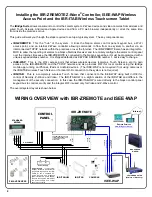
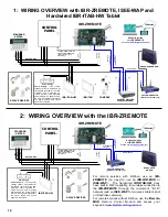
WIRING OVERVIEW with IBR-ZREMOTE and ISEE-WAP
Installing the IBR-ZREMOTE Z-Wave
®
Controller, ISEE-WAP Wireless
Access Point and the IBR-ITAB Wireless Touchscreen Tablet
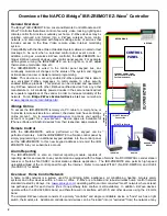
The
iBridge Suite
allows consumers to control their alarm system, Z-Wave devices and video cameras from wireless and
wired Touch Screens, Android and Apple devices and from a PC web browser independently or all at the same time
from inside the premises or out.
This guide will walk you through the steps required to set up a typical system. The key components are:
IBR-ZREMOTE
: This the " hub" of the system. It links the Napco alarm control panel keypad bus, a Wi-Fi
access point, and an internal Z-Wave controller allowing commands to flow from one system to another via an
interconnected TCP/IP network within the premises or over the Internet. The IBR-ZREMOTE also has an integral NL-
MOD to allow the reporting of alarms to a Napco NetLink Receiver and to remotely configure the alarm control panel
over the Internet. Because the IBR-ZREMOTE is connected to the Napco keypad bus, it must be programmed with a
unique keypad address number. It is shipped defaulted as KEYPAD ADDRESS number 1, but is easy to change.
ISEE-WAP
: This is the Wi-Fi access point that allows wireless devices (cameras, Touch Screens, etc.) to gain
access to the IBR-ZREMOTE and the TCP/IP network and also provides Wi-Fi for local control using the iBridge
mobile app running on iPhones, iPads or Android devices. (The ISEE-WAP is not required if not using cameras or
the IBR-ITAB wireless Touch Screen or if a local Wi-Fi connection to the system is not required).
IBR-ITAB
: This is a completely wireless Touch Screen that connects to the ISEE-WAP using built in Wi-Fi for
control of Security, Z-Wave and Video. The IBR-ITAB-HW is a slight variation of the IBR-ITAB and differs in the
management of the security connection. In this case the IBR-ITAB-HW is wired directly to the Napco control panel
keypad bus to control security and the integral Wi-Fi is used only for Video and Z-Wave control.
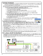
The overall system layout is shown below:
IBR-ZREMOTE
CUSTOMER ROUTER
(Wireless or Wired-only)
KEYPAD BUS
BROADBAND
MODEM
TO PANEL SERIAL PORT (only
needed for IBR-ZREMOTE CS
communication or panel
downloading)
CONTROL
PANEL
STANDARD
KEYPAD
Internet
RED
BLACK
GREE
N
Y
E
LLO
W
GR
EEN
YEL
LO
W
RE
D
BLAC
K
ISEE-WAP
(
(
(
(
(
(
Remote Services
www.ibridgeonline.com
Z-WAVE DEVICES
RE
D
(+)
(–)
BLAC
K
Power Supply
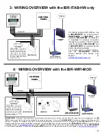
IBR-ITAB-HW
Power Supply
: If the system
standby current is insufficient for
the 380mA required for the IBR-
ITAB-HW, use a separate UL-
Listed Security and Signaling
power-limited 12V power supply.
Be sure the negative terminals of
the power supply and control
panel are connected.
(2) C
A
T5 E
ther
net
C
onnection
(1) C
A
T5 E
thernet
C
onnection
IBR-ITAB
(
(
(
CAMERAS
(3) CAT5 to Router
Summary of Contents for iBridge Suite
Page 18: ...18 NOTES...