

13
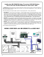
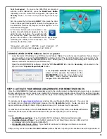
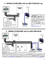
STEP 8: ACTIVATE YOUR IBRIDGE (IBR-ZREMOTE) FOR REMOTE SERVICES
Once the IBR-ZREMOTE has been completely wired to the control panel, configured and powered up, a consumer
iBridge subscriber account is ready to be created for remote services (remote access through the web and remotely
through smartphones), if desired. These activation steps include adding subscribers, cameras and an IBR-ZREMOTE
to a customer account.
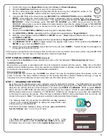
To activate, go to
www.NapcoComNet.com
and log into your NapcoComNet account. If you are not
yet registered as a NapcoComNet dealer, please click the
Registration
button. Dealer accounts are
approved Monday-Friday 8:30am-4:30pm (please allow up to 1 business day for approval).
To activate your new device, click the
Add Device
tab at the top of the screen, click
Service Plans
and
then enter the device's Unit ID / MAC Address for the product type that you are activating.
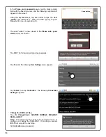
Select:
SLE-GSM Service Plans:
Type the Radio ID# for all Napco SLE-Series Radio models
iSeeVideo Service Plans:
Type the MAC address for all iSeeVideo cameras, IVRs and Vid-
eo Gateways (do not activate the ISEE-WAP)
iBridge/iRemote Service Plans:
Type the MAC address for iBridge and iRemote modules
Simply enter your device’s
Unit ID / MAC address
(without dashes or spaces) and click
Go
to view the applicable ser-
MAC
ADDRESS
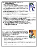
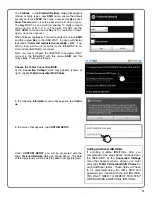
Test the keypad.
To ensure the IBR-ITAB is connected
with the correct ISEE-WAP, press the
Back/Power Button
repeatedly until the Home Screen appears, then press the
Security
button. A screen with your arming choices ap-
pears:
Arm the system by first pressing
AWAY
, then press the User
Code in the keypad that appears. Ensure the keypad text on
the IBR-ITAB matches the keypad text that appears on the
standard wired keypad.
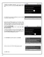
In the Home Screen, when connected, a con-
nection strength indicator appears at the top
right (1-4 bars, as shown). If you wish to verify
the connection, press this icon and text ap-
pears at the bottom of the IBR-ITAB screen
confirming the validity of the connection. For
example, the text may read:
"
Connected with ssid: WAP345, Level: Excellent, IP:
192.168.50.102, Port: 8003, Gateway: 192.168.50.2
"
Signal Strength
Indicator
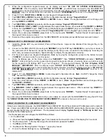
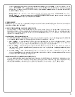
USING NL-MOD CONFIG Software 3.0.2.1 or greater
Verify the correct IP Address to our DNS server as follows:
Note:
You will only need to perform this next step if
you are unable to access the IBR-ZREMOTE remotely and/or if the red LED located on the top center of the
bottom PC board inside the IBR-ZREMOTE is NOT blinking every 15 seconds (this blinking LED normally indi-
cates a successful connection to our DNS server).
Open the NL-MODCONFIG software. Click the "
PC Preset/RCM
" tab, click the
Secondary
tab (located on the
right) and click "
Populate Napco Defaults
" button.
In the
Populate Defaults for Device
popup
(shown at left), populate the defaults for the
IBR-ZREMOTE
(click the radio button and
click
OK
). When finished, download these
changes to the IBR-ZREMOTE.
Summary of Contents for iBridge Suite
Page 18: ...18 NOTES...