


L
NAPCO Security Systems
X
GEM-P3200 Installation Instructions
WI817F 10/05
Page 11
Wiring
Wire keypad(s), zones, expansion zone modules and output devices as shown on the Wiring Diagram. Note that the
Wiring Diagram contains important information not available elsewhere in this manual.
Adding Expansion Zones
GEM-P3200 Series control panels will handle up to 8 zones as is, however this number may be increased to as many as
32 programmable zones using optional expansion zone modules (EZMs).
Wireless Systems
(NOT EVALUATED BY U.L. FOR COMMERCIAL APPLICATIONS)
With the addition of at least one GEM-RECV series receiver, the GEM-P3200 will support up to 48 wireless transmitters.
The panel can accommodate 1-2 receivers within the premises, responding to the one with the stronger transmitter sig-
nal. If any transmitters are selected for the default program, a GEM-RECV receiver will automatically be programmed.
The keypad can display the status of any transmitter, indicating the condition of the zone (normal or open) and transmit-
ter troubles (low battery, tamper or supervisory failure), and signal strength of the last transmission. A receiver failure
will be indicated by “E06-NN” (“no response”, with NN representing the receiver number).
TYPICAL RESIDENTIAL FIRE INSTALLA-
TION (Where permitted by local codes)
At least one smoke detector should be installed directly outside
each sleeping area. If there is more than one floor, additional
smoke detectors should be installed on each level, including the
basement. The living-area and basement smoke detectors
should be installed near the stairway of the next upper level.
For increased protection, additional detectors should be installed
in areas other than those required, such as the dining room, bed-
rooms, utility room, furnace room, and hallways. Heat detectors,
rather than smoke detectors, are recommended in kitchens, at-
tics, and garages due to conditions that may result in false
alarms and improper operation. Large areas and areas with partitions, ceiling beams, doorways, and open joists will re-
quire additional detectors.
Refer to NFPA Standard No. 74 (National Fire Protection Association, Batterymarch Park, Quincy, MA 02269) for addi-
tional information, including proper mounting of detectors.
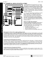
TYPICAL PARTITIONED INSTALLATION
Described and illustrated here are an example of a partitioned system
with common-area protection of the control-panel room. This system
meets UL requirements for a partitioned installation.
•
Both areas must be owned and managed by the same person(s).
•
Both areas must be part of one building at one street address.
•
The control panel and all wiring protecting each partitioned area
must be confined to the respective area and may not encroach upon the
other area. This requires that the control panel room have redundant
protection; that is (a) multiple sets of door contacts, each wired to a
separate zone and (b) one of those zones programmed for each area.
In order to gain access to this protected area without causing an alarm,
both partitions must be disarmed. In lieu of redundant protection, 24-
Hour Zones may be used. Any zone protecting the control panel and
transformer may not be programmed for bypass.
The sounding device must be placed such that the bell test can be
heard by all partitions. Note: NFPA 74 (Household Fire Warning Equipment) requires that a fire alarm audible device be
installed indoors. The User Program Code is not to be given to anyone except the authority responsible for all partitions.
CAUTION:
Do not run telephone wiring near speaker wires; do not run keypad wiring with loop wiring.
INS
T
A
L
L
A
TION
Summary of Contents for Gemini GEM-P3200
Page 58: ...X GEM P3200 Installation Instructions L NAPCO Security Systems WI817F 10 05 Page 58 NOTES...
Page 66: ...X GEM P3200 Installation Instructions L NAPCO Security Systems WI817F 10 05 Page 66 Notes...
Page 67: ...L NAPCO Security Systems X GEM P3200 Installation Instructions WI817F 10 05 Page 67 Notes...


