


11
been selected as an
Exit/Entry Follower Zone
,
Home/Away with Delay Zones,
or
24 Hour Zone
.
A8
+ User 1 Code - User Program
Mode
A9
Keypad Sleep Mode ON/OFF
Enter this command to turn the keypad sounder
ON/OFF. When the keypad is in Sleep mode all
keypad sounds will be silenced except for key-
pad feedback beeps and Keypad Sounder on
Alarm.
User Commands - Optional
A0
Easy Exit
If enabled in Dealer programming, enter this
command while the panel is Armed to allow 3
minutes to exit the premises through
Exit/Entry
and
Exit/Entry Follower Zones
.
A3
Access on PGM
If enabled in Dealer programming, enter this
command to activate the PGM output (Terminal
15) for 5 seconds.
Dealer Commands
A6
Download
(Programming Required)
Establish a connection between the PCD phone
line and the Control Panel phone line. When
ready, tell the installer to arm, then disarm.
Then enter
A6
in order to establish a
connection. Phone connection to installer will
go "dead" as downloader and panel connect.
A7
Fault Find ON/OFF
Hardwired Zone Operation
Enter this command to turn Fault Find ON/OFF.
While in Fault Find mode, the loop response for
all zones will be set to the faster response of 40
ms. The keypad will beep for .25-seconds when
hardwired zones are faulted and for 1-second
when zones are restored.
Wireless Operation
(Signal Strength)
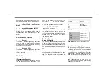
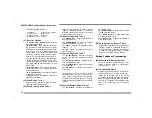
While in Fault Find mode the keypad will provide
an audible (Table 6) and visual (Figure 5) indi-
cation of each transmitter's signal strength. The
signal strength metering is based on a scale of 4
to 10, with 4 being marginal and 10 being excel-
lent.
The keypad will beep out a number, from 1-4,
corresponding to the signal strength of the trans-
mitter. See Table 6. Each beep is 1-second
long. The keypad will sound a short beep for
transmitters with signal strengths of 3 or less.
Signal Strength Logging Mode
The Signal Strength Logging Mode is a trouble-
shooting tool which allows the collection of sig-
nal strength information for all transmitters on
the system. Normally the Signal Strength of Su-
pervisory Signals are not logged; during Signal
Strength Logging Mode the signal strength infor-
mation for all supervisory signals received over
a two hour period will be saved to the LOG.
Local Activation
Enable [92-4=ON], this will initiate a two hour
test period where all supervisory signals will log
signal strength information.
Signal Strength = 8-10
Signal Strength = 6-7
Signal Strength = 4
Signal Strength = 5
1
1 2
1 2 3
1 2 3 4
FIGURE
5
V
ISUAL
S
IGNAL
S
TRENGTH
I
NDICATION
TABLE
6
A
UDIBLE
S
IGNAL
S
TRENGTH
I
NDICATION
SIGNAL STRENGTH
KEYPAD SOUNDER
3 or less
.25s BEEP
4
BEEP
5
BEEP BEEP
6-7
BEEP BEEP BEEP
8-10
BEEP BEEP BEEP BEEP


