background image

75

Test Mode

7. Troubleshooting

Troubleshooting

Disassembling/Replacement Procedure

- Must be performed by a technician -

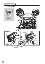
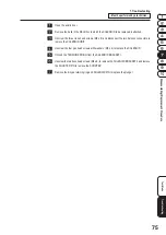
  Open the acrylic door.

  Remove the balls in the REL RAIL to which the SOLENOID to be replaced is attached.

  Unscrew the three truss head screws (M4 x 6) and disconnect the two harness connectors to 

remove the SOLENOID UNIT.

  Unscrew the four pan head screws with washers (M3 x 6) to replace the SOLENOID.

  Unhook the TENSION SPRING from the SOLENOID BRACKET 1.

  Unscrew the two truss head screws (M4 x 6) to remove the SOLENOID BRACKET 3 and remove 

the SHOOTER PIN to remove the SHOOTER.

  Remove the E-type retaining ring and SOLENOID PIN to replace the plunger.

Summary of Contents for PAC-MAN SWIRL

Page 1: ...r needed The actual product may differ slightly from the illustrations in this Operation Manual PAC MAN SWIRL NAMCO BANDAI Games Inc The machine specifications or the information in this Operation Man...

Page 2: ...in light injury or damage to other property Notes about functionality that are not linked to safety are indicated by the following symbol Information about product functions or protection Definition...

Page 3: ...y result in electric shock or electrical leakage z z Do not touch the power cord plug with wet hands It may result in electric shock z z The power capacity of the machine is maximum current consumptio...

Page 4: ...e machine in an appropriate location with ample illumination and keep the labels clean at all times Make sure that the labels are not hidden by other game machines or objects Do not remove or alter th...

Page 5: ...ounded three wire outlet Do not use a cheater plug or cut off the ground pin on the line cord ELECTRICAL SHOCKS Disconnect AC power before servicing Verify that there is a working ground connection If...

Page 6: ...2 3 Points for Function Inspection After Power On 23 5 Test Mode 24 5 1 Service Panels 24 5 2 Basic Operation MAIN MENU 26 5 3 Checking Logs DATA MENU 27 5 3 1 INCOME DATA 28 5 3 2 WIN COUNT 29 5 3 3...

Page 7: ...R MOTOR DRIVE PC BOARD 65 7 3 8 SHUTTER POSITION SHUTTER ORIGIN SENSOR 66 7 3 9 TABLE DRIVE MOTOR 67 7 3 10 TABLE POSITION SENSOR TABLE ORIGIN SENSOR 68 7 3 11 JACKPOT SLOPE SLOPE SENSOR Receiver Tran...

Page 8: ...oduct Specifications 1 Rated power supply 100 to 240 V AC 50 60 Hz 2 Rated power consumption 280 W 3 Dimensions Width W 1 490 x Depth D 1 490 x Height H 2 240 mm 1 490 mm 1 490 mm 2 240 mm 2 050 mm 1...

Page 9: ...se 1 Cabinet assembly Width W 1 200 x Depth D 1 200 x Height H 2 050 mm Weight 300 kg 2 3 Pillar assembly Width W 410 x Depth D 1 630 x Height H 90 mm Weight 16 kg 4 Control panel assembly Width W 390...

Page 10: ...t assembly 1 2 Service key Taped on the cabinet 2 3 Cash box key Taped on the cabinet 2 2 3 Pillar assembly Package contents No Name Specification Qty 1 Pillar assembly 4 2 per package 4 Control panel...

Page 11: ...anual 1 3 Pocket sticker 2 6 AC POWER CORD type B for 110 V AC 1 7 AC POWER CORD type G for 230 V AC 1 8 CASHFLOW selector option wire harness 4 9 Cable tie 8 10 DOOR BAR A 4 11 DOOR BAR B 4 12 COIN R...

Page 12: ...shock or fire z z Fully insert the power cord plug into the outlet Poor contact may generate heat and result in a fire or burns z z Be sure to install the ground wire Failure to install the ground wir...

Page 13: ...ay zone around the machine so that players do not bump into bystanders or passersby Leave a space of 1 m or more between the machine and the wall or other machines so that parts can be removed when pe...

Page 14: ...y for Station 4 green Opposite side Station 2 blue for Station 1 yellow Opposite side Station 3 red Control panel assembly Jackpot display JPD assembly Spiral assembly Field assembly Cabinet base asse...

Page 15: ...Names Must be performed by a technician Inner structure upper section Jackpot display JPD assembly Spiral assembly Field assembly Allocator unit 7 SEG LED PC BOARD LARGE Ball stock release section Tab...

Page 16: ...e box see page 17 Coin assembly Ticket assembly DOOR BAR selectable Core assembly Ball slope Code box assembly Service panel LIFTING MOTOR SHUTTER MOTOR TABLE DRIVE MOTOR Ball slope BALL SHUTTER Field...

Page 17: ...TCHING REGULATOR 12 V SWITCHING REGULATOR 24 V SWITCHING REGULATOR 5 V MAIN PC BOARD SHUTTER MOTOR DRIVE PC BOARD LIFTING MOTOR DRIVE PC BOARD ALLOCATOR MOTOR DRIVE PC BOARD Inside Station 2 blue Insi...

Page 18: ...e two flange lock nuts M4 onto the stud bolts on the wider side of the pillar assembly Pass the harness connector through the hole in the cabinet corner and hook the two stud bolts using the flange lo...

Page 19: ...re the pillar assembly using the six flange lock nuts M4 and the two nuts from Step Open the MAINT DOOR A or MAINT DOOR C and the TICKET DOOR Connect the pillar assembly harness connector to the cabin...

Page 20: ...e color must match those of the 7 SEG LED ACRYL 7 SEG LED ACRYL Wing bolt M4 x 10 AC CORD SHUTTER Harness connector 8 pin Open the MAINT DOOR A pass the power cord through the slit on the bottom of th...

Page 21: ...he machine correctly may result in a fire electric shock injury or malfunction z z The warning labels attached to the machine contain important information for ensuring safety Be sure to observe the f...

Page 22: ...ecified play zone provided See 3 3 Play Zone for Installation on page 13 5 Is the power cord laid out safely so that it will not cause players or other customers to trip over it 6 Is the power cord se...

Page 23: ...cking Machine Operation I O TEST on page 40 2 Check the switch inputs See SERVICE PANELTEST and SW SENSOR TEST in 5 5 Checking Machine Operation I O TEST on page 41 3 Check the field assembly function...

Page 24: ...el In Test mode a variety information such as game logs error logs machine settings and so on is displayed on this panel See 5 2 through 5 5 for details In normal mode the following information is dis...

Page 25: ...tton to enter or execute the selection F BACK button Press this button to return to the previous item or setting G UP DOWN button Press these buttons to select an item or setting numerical value A SER...

Page 26: ...n the TEST switch to OFF to exit Test mode 1 2 3 4 5 6 Item Description 1 DATA Displays a variety of data logs and resets them See 5 3 for details 2 OPTIONS Displays a variety of data logs and resets...

Page 27: ...eturn to the MAIN MENU screen Item Description 1 INCOME DATA Displays the total INCOME DATA of all stations or those for each station See 5 3 1 for details 2 WIN COUNT Displays the total number of win...

Page 28: ...the BACK button to return to the MAIN MENU screen Pressing the UP DOWN button to select NEXT and pressing the ENTER button is another way to go to the next page Item Description 1 COIN IN Displays the...

Page 29: ...menu item consists of a page for the total number of INCOME DATA of all stations and those for each station To go to the next page press the ENTER button After checking logs press the BACK button to r...

Page 30: ...DRIVE MOTOR 2 SHUTTER Displays the number of operating times of the SHUTTER MOTOR 3 LIFT Displays the number of operating times of the LIFTING MOTOR 4 ALLOCATE Displays the number of operating times...

Page 31: ...ot sticker denotes the I pocket This menu item consists of pages for each station To go to the next page press the ENTER button After checking logs press the BACK button to return to the MAIN MENU scr...

Page 32: ...ER button After checking logs press the BACK button to return to the MAIN MENU screen Pressing the UP DOWN button to select NEXT and pressing the ENTER button is another way to go to the next page Des...

Page 33: ...TORY data Press the ENTER button Y Yes N No appears next to the menu item DATA CLEAR Press the UP DOWN button to select Y Yes and press the ENTER button to reset the data CLEAR flashes for approx two...

Page 34: ...ss the BACK button to return to the MAIN MENU screen 1 2 3 4 5 6 Item Description Default setting 1 DISC TYPE Sets the dividend for the roulette in use The dividend varies depending on the DISC TYPE A...

Page 35: ...ription Default setting 7 JP START Sets the number of tickets that triggers jackpot accumulation 100 150 200 250 300 350 9950 9999 tickets 1000 8 JP MAX Sets the maximum number of tickets that can be...

Page 36: ...f the sound effects other than the BGM sound 00 min to 15 max 10 15 JP VOLUME Sets the jackpot win sound volume 00 min to 15 max 10 16 ERROR VOLUME Sets the error sound volume 00 min to 15 max 10 17 A...

Page 37: ...is executed After all tests complete press the BACK button to return to the MAIN MENU screen Item Description 1 DISC MOTOR FWD Drives the DISC MOTOR to rotate the ROTARY TABLE clockwise 2 DISC MOTOR...

Page 38: ...R Displays the SHUTTER ORIGIN SENSOR status 9 POSITION SENSOR Displays the SHUTTER POSITION SENSOR status 10 ENTRANCE SENSOR Displays the BALL DETECTING SENSOR status 11 12 13 14 Item Description 11 L...

Page 39: ...verse 17 ORIGIN SENSOR Displays the ALLOCATE ORIGIN SENSOR status 18 POSITION SENSOR Displays the ALLOCATE POSITION SENSOR status 19 20 21 Item Description 19 SHOT SOLENOID1 to 4 Activates the SOLENOI...

Page 40: ...PUSH START switch ILLUMINATED SWITCH for the corresponding station is being pressed 23 ST1 to 4 Displays the number of times of detection made by the TICKET SENSOR for each station 24 Item Description...

Page 41: ...ENTER button and either of the UP DOWN button to return to the I O TEST screen Item Description 26 SERVICE PANEL TEST Displays the status of the following controls displayed on the service panel UP bu...

Page 42: ...n to return to the MAIN MENU screen Item Description 1 SHOT TEST Executes the ball shooting test See 5 6 1 for details 2 BALL SUPPLY Executes the ball replenishing function See 5 6 2 for details 5 6 1...

Page 43: ...ert a ball after confirming that the previously inserted ball has been lifted up in the INNER RAILs located at the center of the machine Be sure to insert the exact number of 26 balls Otherwise an err...

Page 44: ...the ENTER button is pressed the next sound is selected and the sound or sound effect is previewed If necessary repeat steps and to set the sound After all settings complete press the BACK button to r...

Page 45: ...ess the UP DOWN button to select a station and press the ENTER button Press the UP DOWN button to select Y Yes and press the ENTER button to initialize reset the data CLEAR flashes for approx two seco...

Page 46: ...adjusters are securely locked Power cord Check if the power cord plug is securely inserted into the power socket in the cord box Remove any dust or dirt on the plug Check if there is no crack or dirt...

Page 47: ...t or injury to yourself or others as well as damage to the electronic circuitry be sure to turn off the power switch before starting this task Do not use thinner benzene gasoline alcohol or other orga...

Page 48: ...on the same station the latest error is displayed Due to the limit on the number of characters that can be displayed the error indication may not be fully displayed In cases of station errors the erro...

Page 49: ...49 Test Mode 7 Troubleshooting Troubleshooting Error Display Must be performed by a technician When starting the machine Check type and status Ex During machine initialization...

Page 50: ...operation and automatically recovers An on off setting for the retrial option is available on the DISC RETRY menu See page 35 If the machine does not recover remove the jammed balls The URETHANE ROLLE...

Page 51: ...ATOR ORIGIN SENSOR See page 72 ALLOCATOR MOTOR DRIVE PC BOARD failure Replace the ALLOCATOR MOTOR DRIVE PC BOARD See page 72 ALLOCATOR MOTOR failure Replace the ALLOCATOR MOTOR See page 72 007 SHUT PO...

Page 52: ...page 62 LIFTING MOTOR failure Replace the LIFTING MOTOR See page 62 011 LIFT ENT No balls to be lifted error No balls to be lifted Replenish balls The balls jammed in the ball slope Remove the balls T...

Page 53: ...AM G Station 4 Green 118 SHOT SEN Y Station 1 Yellow BALL RELEASE SENSOR unpassed error The balls jammed Remove the balls 218 SHOT SEN B Station 2 Blue BALL RELEASE SENSOR failure Replace the BALL REL...

Page 54: ...C BOARD flash and the error log is recorded however the game is not interrupted by the error Slip the end of a ticket roll through the dispenser The machine automatically recovers 222 T EMPTY B Statio...

Page 55: ...mmed on the outer ball slope Remove the balls 226 SLO OUT B Station 2 Blue 326 SLO OUT R Station 3 Red JACKPOT SLOPE SENSOR failure Replace the JACKPOT SLOPE SENSOR See page 69 426 SLO OUT G Station 4...

Page 56: ...articular when sending the MAIN PC BOARD wrap the part in sponge or air bubble wrapping before packing it in a cardboard box to make sure that the part is not exposed to external forces 7 2 1 General...

Page 57: ...failure Replace the LED LAMP MAIN PC BOARD failure Replace the MAIN PC BOARD 59 The game does not start even when sufficient coins are inserted COIN SELECTOR failure Replace the COIN SELECTOR MAIN PC...

Page 58: ...DOOR SENSOR Cabinet base assembly DOOR SENSOR BRACKET DOOR SENSOR Pan head screw M3 x 12 Flange lock nut M4 Open the acrylic door Disconnect the harness connector and unscrew the two flange lock nuts...

Page 59: ...screw w washers M3 x 6 Station 3 red MAIN PC BOARD Harness connector Harness connector Open the ticket door on Station 4 green to create workspace Remove the MAINT DOOR C on Station 3 red using the s...

Page 60: ...th washers M4 x 8 to remove the PS COVER Unscrew the four pan head screws with washers M4 x 8 and disconnect five harness connectors to remove the PS BASE with the switching regulators still secured t...

Page 61: ...NG SENSOR make sure that the sensor orientation is as in the figure Remove the MAINT DOOR C on Station 2 blue using the service key Loosen the four pan head screws with washers M4 x 6 to remove the GU...

Page 62: ...hub and slider LIFTING MOTOR Pan head screw M5 x 12 Station 4 green Pan head screw M3 x 6 LIFTING MOTOR DRIVE PC BOARD w red mark Coupling hub Coupling the shafts Coupling slider Lifting motor shaft...

Page 63: ...LATOR on page 60 Unscrew the four pan head screws with washers M4 x 6 and disconnect the three harness connectors from the LIFTING MOTOR DRIVE PC BOARD to remove the LIFT BRACKET B Unscrew the two set...

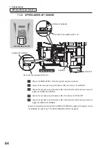
Page 64: ...pan head screws with washers M4 x 6 to remove the GUARD R Unscrew the pan head screw with washers M3 x 12 and disconnect the harness connector to replace the UPPER LIFT SENSOR Unscrew the pan head sc...

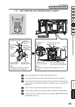
Page 65: ...E PC BOARD w orange mark Station 2 blue Remove the MAINT DOOR C on Station 2 blue using the service key Loosen the upper two pan head screws with washers M4 x 6 to remove the GUARD F Unscrew the four...

Page 66: ...INT DOOR C on the station 4 green using the service key Loosen the upper two pan head screws with washers M4 x 6 to remove the PS COVER and GUARD R Unscrew the two pan head screw with washers M4 x 6 a...

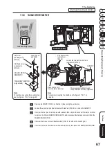
Page 67: ...w washers M4 x 8 Station 2 blue Remove the MAINT DOOR C on Station 2 blue using the service key Loosen the upper two pan head screws with washers M4 x 6 to remove the GUARD F Unscrew the four pan hea...

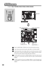
Page 68: ...e GUARD F Unscrew the pan head screws with washers M5 x 12 unscrew the four pan head screws with washers M5 x 12 that secure the BALLSLOPE UNIT to the MIDDLE PLATE and disconnect the harness connector...

Page 69: ...d from the lower angle Viewed from the lower angle Remove the MAINT DOOR UNIT or the MAINT DOOR C on the stations located on both side of the BALLSLOPE UNIT that needs a replacement sensor If necessar...

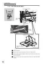
Page 70: ...connector Truss head screw M4 x 15 Pan head screw w washers M3 x 6 7 SEG LED CASE Open the acrylic door Unscrew the two truss head screws M4 x 6 to remove the 7 SEG LED ACRYL Unscrew the two truss hea...

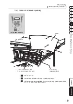
Page 71: ...display assembly JPD AC 7 SEG LED PC BOARD LARGE The connector is located on the back Pan head screw w washers M3 x 6 Truss head screw M4 x 6 Open the acrylic door Unscrew the six truss head screws M...

Page 72: ...L ALLOCATE UNIT Pan head screw w washers M4 x 6 PART MTR BRACKET Set screw double points M4 x 6 ALLOCATOR MOTOR w gearhead Coupling hub and slider ALLOCATOR MOTOR DRIVE PC BOARD w orange mark Pan head...

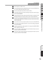
Page 73: ...e harness connector to remove the BALL ALOCATE UNIT Unscrewthefourpanheadscrewswithwashers M4x6 disconnectthethreeharnessconnectors from theALLOCATOR MOTOR DRIVE PC BOARD and disconnect the faston ter...

Page 74: ...3 15 SOLENOID Spiral assembly Truss head screw M4 x 6 Pan head screw w washers M3 x 6 SOLENOID SOLENOID UNIT REL RAIL TENSION SPRING SOLENOID BRACKET 1 SHOOT PIN SOLENOID BRACKET 3 Truss head screw M...

Page 75: ...he three truss head screws M4 x 6 and disconnect the two harness connectors to remove the SOLENOID UNIT Unscrew the four pan head screws with washers M3 x 6 to replace the SOLENOID Unhook the TENSION...

Page 76: ...w w washers M3 x 6 Pan head screw w washers M3 x 12 BALL RELEASE SENSOR Open the acrylic door Unscrew the two truss head screws M4 x 6 and disconnect the harness connectors to remove the SENSOR BASE B...

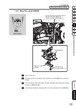
Page 77: ...x 6 The other screw is located on the opposite side of the SENSOR BASE A BALL FULL LOAD SENSOR SENSOR BASE A Open the acrylic door Remove the balls in the REL RAIL to which the BALL FULL LOAD SENSOR...

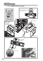
Page 78: ...D SWITCH LED LAMP Control panel assembly MAINT DOOR Pan head screw w washers M4 x 8 View from under the control panel assembly Loosen the two pan head screws w washers M4 x 25 Control panel assembly I...

Page 79: ...ad screws with washers M4 x 8 that secure the control panel assembly Open the acrylic door assembly of the station that needs a replacement ILLUMINATED SWITCH Loosen the two pan head screws with washe...

Page 80: ...sposal z z When disposing of the machine follow the applicable regulations for collection transportation and disposal z z In such cases make sure that each operation is delegated to specialists in tha...

Page 81: ...R BAR A 4 734501 2 DOOR BAR B 4 734502 3 AC POWER CORD type B 1 for 110 V AC 2 4 m 734503 4 AC POWER CORD type G 1 for 230 V AC 2 4 m 703504 5 Operation Manual 1 703500 6 BALL 30 incl 4 spare balls 70...

Page 82: ...9 Parts List 82 9 2 Jackpot Display JPD Assembly 10 13 15 14 2 10 4 7 9 5 1 1 16 12 6 7 8 3 3 5 1 1 7 15 6 11 11 14 16 16 16 14 12 12 9 7 4 17 10 2 14 11...

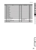
Page 83: ...1 4 734513 5 JPD HOLDER 1 4 734514 6 JPD ROOF 4 4 734515 7 JPD ROOF 5 8 734516 8 JPD END PLATE 1 734517 9 JPD ROOF 3 4 734518 10 JPD HOLDER 3 3 734519 11 JPD PILLAR 2 4 734520 12 JPD PILLAR 1 4 734521...

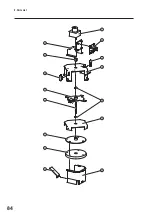
Page 84: ...9 Parts List 84 27 29 28 18 19 25 26 24 21 23 22 28 31 20 30...

Page 85: ...1 PARTED PLATE A 1 734529 22 PARTED SENSOR DG 1 734530 23 PARTED PIN 1 734531 24 PARTED PLATE B 1 734532 25 PARTED BOX 1 734533 26 SORTER BRACKET 6_1 1 734534 27 ALLOCATOR MOTOR 1 TG 05J BE 150 F1332...

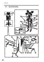
Page 86: ...9 Parts List 86 9 3 Spiral Assembly 9 8 5 5 5 3 19 4 2 3 1 2 3 19 4 19 2 2 4 19 18 6 18 17 4 3 13 14 15 16 11 12 10 7 7 13 10 7 10 1 5...

Page 87: ...4539 6 PARTITION 4 734540 7 REL PILLAR B 4 734541 8 RELEASE BASE 1 734542 9 RELEASE BASE 2 1 734543 10 REL PILLAR 4 734544 11 LAMP BRACKET A 4 734545 12 HGN BRACKET 4 734546 13 RAIL TOP BRACKET 4 7345...

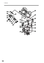
Page 88: ...9 Parts List 88 39 31 40 29 25 26 22 27 34 23 35 24 21 28 37 20 30 38 32 36 33 40...

Page 89: ...SHOOTER 4 734554 27 SHOOT STOPPER 4 734555 28 SOLENOID PIN 4 734556 29 SENSOR BASE B 4 734557 30 SENSOR BRACKET A 4 734558 31 POM HINGE 8 734559 32 SHAFT BRACKET 8 734560 33 SENSOR ACT BM 4 734561 34...

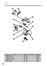
Page 90: ...90 41 39 40 36 42 40 38 43 32 31 44 45 No Name Qty Type and rating Part No 41 SENSOR BASE A 4 734563 42 SENSOR BRACKET B 4 734564 43 SENSOR ACTUATOR 4 734565 44 BALL GUIDE BRACKET 4 734566 45 BALL GUI...

Page 91: ...4 734570 49 SLOWDOWN BRACKET 2 4 734571 50 SLOWDOWN ARM BRACKET 2 4 734572 51 SLOWDOWN STOPPER 2 4 734573 52 BALL RAIL 4 734574 53 BALL OUT ACRYL YELLOW 4 Station 1 734576 54 RAIL RING 4 734577 55 SL...

Page 92: ...rt No 1 MIDDLE PLATE 1 734579 2 7 SEG LED CASE 4 734580 3 7 SEG LED ACRYL YELLOW 1 734581 4 7 SEG LED ACRYL BLUE 1 734582 5 7 SEG LED ACRYL RED 1 734583 6 7 SEG LED ACRYL GREEN 1 734584 7 CASTER BRACK...

Page 93: ...T C 4 734589 13 SLOPE BRACKET D 4 734590 14 SLOPE BRACKET E F 4 734591 15 SLOPE BRACKET G H 4 734592 16 SLOPE BRACKET K 4 734593 17 SLOPE BRACKET L 4 734594 18 SLOPE BOTTOM COVER 4 734595 19 SLOPE COV...

Page 94: ...1 No Name Qty Type and rating Part No 25 ROTARY TABLE 1 734600 26 ROTARY JOINT RING 1 734601 27 ROULETTE 2 734602 28 ROULETTE BRACKET 1 4 734603 29 ROULETTE BRACKET 2 2 734604 30 ROULETTE BRACKET 4 2...

Page 95: ...95 Field Assembly 35 36 33 34 36 37 No Name Qty Type and rating Part No 33 INNER WALL 1 4 734608 34 INNER WALL 2 4 734609 35 OUTER WALL 1 4 734610 36 OUTER WALL BRACKET 8 734611 37 LED TAPE 700 mm 4...

Page 96: ...9 Parts List 96 9 5 Core Assembly 8 7 6 7 5 3 2 9 10 14 11 13 15 14 12 4 1 6 8...

Page 97: ...AME A 1 734615 4 UNDER FRAME B 1 734616 5 MIDDLE FRAME A 1 734617 6 MIDDLE FRAME B 2 734618 7 MIDDLE RAIL 4 734619 8 MIDDLE RAIL B 4 734620 9 MIDDLE ROLLER 3 734621 10 MIDDLE PIN A 3 734622 11 MIDDLE...

Page 98: ...9 Parts List 98 34 35 23 17 32 29 16 27 26 28 36 24 17 18 25 19 31 32 32 32 33 30 37 21 20 22 33...

Page 99: ...34633 24 LIFT RING 1 734634 25 LIFT PLUNGER A 1 734635 26 LIFT PLUNGER B 1 734636 27 LIFT PLUNGER C 1 734637 28 LIFT SENSOR BRACKET 1 734638 29 LIFT ARM 1 734639 30 COUPLING 1 MCOLK20 8 8 107195 31 BE...

Page 100: ...9 Parts List 100 38 46 58 47 58 45 46 58 47 58 50 61 48 49 51 53 42 58 43 56 52 59 44 60 41 55 39 45 46 58 47 58 46 58 58 47 55 54 32 32 58 40 57 58 40 57...

Page 101: ...34648 47 RING OUTER ROLLER B 4 734649 48 SHUTTER SENSOR BRACKET A 1 734650 49 SHUTTER SENSOR BRACKET C 1 734651 50 BALL SHUTTER 1 734652 51 ROTARY RING 2 734653 52 SHUTTER SENSOR DG A 1 734654 53 SHUT...

Page 102: ...9 Parts List 102 62 64 75 58 73 74 58 75 58 74 58 66 71 61 51 42 69 55 58 43 70 58 40 41 55 39 61 72 66 75 63 58 74 67 68 65 54 32...

Page 103: ...RY SENSOR DG 1 734661 66 ROLLER SUPPORT 2 734662 67 ROLLER MOTOR BRACKET D 1 734663 68 TABLE DRIVE MOTOR 1 TG MX2034 55 BM 150 R2193 24V 005543 69 COUPLING 1 MCO20 6 8 107196 70 COMPRESSION SPRING 4 S...

Page 104: ...9 Parts List 104 9 6 Cabinet Base Assembly 7 15 8 9 10 11 13 6 14 14 10 8 9 8 1 2 12 3 13 14 5 4 13...

Page 105: ...72 4 MAINT DOOR B 1 734673 5 ERROR LABEL 1 734674 6 MAINT DOOR C 3 734675 7 DOOR SENSOR BRACKET 4 734676 8 WARNING LABEL Maintenance B EXP 4 461539 9 FORK DECAL PH 4 461678 10 ADJUSTER 4 D B3 16 100 1...

Page 106: ...32 32 27 27 43 43 49 49 38 38 50 50 42 42 26 26 28 28 29 29 30 30 46 46 48 48 47 47 31 31 33 33 24 24 17 17 17 17 17 17 52 52 53 53 39 39 51 51 37 37 45 45 40 40 36 36 54 54 41 41 18 18 22 22 21 21 20...

Page 107: ...C BOARD BOX 1 734697 35 PC BOARD LID 1 734698 36 SWITCH PANEL 1 734699 37 VFD AC 1 734505 38 MAINT BOX 1 734677 39 SLIDE LABEL 1 734678 40 COUNTER LABEL 1 734750 41 AC IN LABEL 1 734751 42 INLET LABEL...

Page 108: ...9 Parts List 108 9 7 Acrylic Door Assembly 22 14 22 13 12 15 20 1 8 6 11 3 16 22 18 17 19 9 10 4 5 7 1 2 21...

Page 109: ...OORFRAME F 4 734761 7 DOOR AC 4 734762 8 DOOR SENSOR DG 4 734763 9 DOOR ROD 8 734764 10 DOOR LOCK 4 734765 11 DOOR HINGE 4 734766 12 DOOR BRACKET A 4 734767 13 DOOR PIN A 4 734768 14 DOOR BAR 4 734769...

Page 110: ...llar Assembly 3 1 2 4 5 No Name Qty Type and rating Part No 1 PILLAR AC 4 734776 2 PILLAR BRACKET 1 4 734777 3 PILLAR BRACKET 2 4 734778 4 PILLAR BRACKET 3 4 734779 5 LED TAPE 1 400 mm 4 5050RGB D1672...

Page 111: ...ANEL AC YELLOW 1 Station 1 734781 3 CONTROL PANEL AC BLUE 1 Station 2 734782 4 CONTROL PANEL AC RED 1 Station 3 734783 5 CONTROL PANEL AC GREEN 1 Station 4 734784 6 SWITCH SHEET YELLOW 1 Station 1 734...

Page 112: ...112...

Page 113: ...WH GN WH BU WH VT WH GY WH BK PK LT BU PK LT BU BN GN BN GN OG AWG22 A L AWG22 A L AWG22 A L TIN CNT TOUT CNT 58 58 57 57 BN GN VFD VCC SIN GND SBUSY N C RESET 1 1 3 3 4 4 2 2 5 5 6 6 J22 XH6P BK AWG1...

Page 114: ...G22 A L MAIN PCB 2 9 DISPLAY BODY ASSY OG BK J36 YL4P 4 4 3 3 1 1 2 2 AWG20OG AWG20BK LP3 DISITAL TAPE LIGHT DISPLAY BODY UPPER 12V 13W 2000mm 12V DATA CLK GND 1 1 3 3 4 4 2 2 J37 XA4P AWG20BU AWG20VT...

Page 115: ...1 2 2 SEN07 KI1300 AA07LF BALL FULL CHECK SENSOR 3 1 1 3 3 2 2 5V GND SIG SEN08 KI1300 AA07LF BALL RELEASE CHECK SENSOR 3 1 1 3 3 2 2 5V GND SIG J42 XH3P YE OG AWG22 A L AWG22 A L SOL03 BALL RELEASE S...

Page 116: ...1 1 2 2 24V GND J105 VH2P 1 1 3 3 2 2 MOTOR MOTOR J106 VH3P AWG22 A L AWG22 A L RD BK 1 1 3 3 2 2 5V GND SIG J102 XH3P 1 1 3 3 2 2 5V GND SIG J103 XH3P BK RD WH PK AWG16 GN YE BK YE BK YE BK YE SEN27...

Page 117: ...3 GY WH 1 1 3 3 4 4 2 2 5 5 6 6 7 7 8 8 9 9 10 10 11 11 12 12 YL12P 3x4 AWG16GN YE YL6P YL12P OG OG WH BN WH BN GN GN BK J109 YL3P OG WH YE GY 1 1 3 3 4 4 2 2 5 5 XA5P OG BN BK WH BN GY BK OG BN GY WH...

Page 118: ...YE AWG16GN YE J61 XA4P WH OG WH YE WH OG WH YE WH YE WH RD WH J15 CN E XH8P 3 3 SPI LED2 B 1 1 3 3 4 4 J183 2 2 5 5 6 6 7 7 8 8 9 9 10 10 11 11 12 12 YL12P 3x4 1 3 4 2 5 6 7 8 9 10 11 12 J129 1 3 4 2...

Page 119: ...5 6 J147 YL6P YL12P OG OG GN GN J181 XA5P OG BU BK WH OG PK SERVICEPANEL ASSY AWG16GN YE OG BK AWG20 BK AWG20 OG OG BU GN PK BN AWG16GN YE BK WH OG BK GY WH WH OG OG WH VT BN BU GN PK COIN SE3 3 CN A...

Page 120: ...N J193 XA5P OG BN BK WH BN GY SERVICEPANEL ASSY AWG16GN YE OG BK AWG20 BK AWG20 OG OG BU GN PK WH GY VT AWG16GN YE WH YE VT LT BU BK WH YE VT LT BU BK GY WH OG VT BU GN PK COIN SEN4 4 CN A J12 HIF3 64...

Page 121: ...CLK GND 1 3 4 2 XA4P 1 3 4 2 AWG22 A L AWG22 A L AWG22 A L AWG22 A L AWG22 A L AWG22 A L AWG22 A L AWG22 A L AWG22 A L AWG22 A L AWG22 A L AWG22 A L AWG22 A L AWG22 A L AWG22 A L AWG22 A L AWG22 A L...

Page 122: ......

Page 123: ......

Page 124: ......

Page 125: ......

Reviews: