73
Test Mode
7. Troubleshooting
Troubleshooting
Disassembling/Replacement Procedure
- Must be performed by a technician -
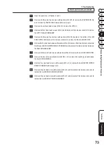
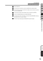
Open the acrylic door of Stations 1 and 3.
Unscrew the three pan head screws with washers (M4 x 25) to remove the PARTED BOX. Be
sure to rotate the PARTED BOX slowly while removing it.
Unscrew the six truss head screws (M4 x 6) to remove the JPD AC.
Unscrew the four truss head screws (M4 x 4) and disconnect the harness connector to remove
the JPD 7-SEG LED BRACKET.
Unscrew the three pan head screws with washers (M4 x 25) located on the bottom of the JPD
END PLATE and disconnect the harness connector to remove the BALL ALOCATE UNIT.
Unscrew the four pan head screws with washers (M4 x 6), disconnect the three harness connectors
from the ALLOCATOR MOTOR DRIVE PC BOARD, and disconnect the faston terminal to remove
the PART MTR BRACKET.
Unscrew the four pan head screws with washers (M4 x 8) to remove the ALLOCATOR MOTOR.
Unscrew the two set screws (double points) (M4 x 6) to remove the coupling hub and replace
the ALLOCATOR MOTOR.
Unscrew four pan head screws with washers (M3 x 6) to replace the ALLOCATOR MOTOR
DRIVE PC BOARD with orange mark.
Unscrew the pan head screw with washers (M3 x 12) and disconnect the harness connector to
replace the ALLOCATOR ORIGIN SENSOR.
Unscrew the pan head screw with washers (M3 x 12) and disconnect the harness connector to
replace the ALLOCATOR POSITION SENSOR.
Summary of Contents for PAC-MAN SWIRL
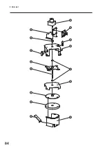
Page 84: ...9 Parts List 84 27 29 28 18 19 25 26 24 21 23 22 28 31 20 30...
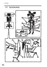
Page 88: ...9 Parts List 88 39 31 40 29 25 26 22 27 34 23 35 24 21 28 37 20 30 38 32 36 33 40...
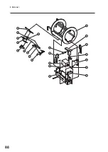
Page 96: ...9 Parts List 96 9 5 Core Assembly 8 7 6 7 5 3 2 9 10 14 11 13 15 14 12 4 1 6 8...
Page 112: ...112...
Page 122: ......
Page 123: ......
Page 124: ......
Page 125: ......


